
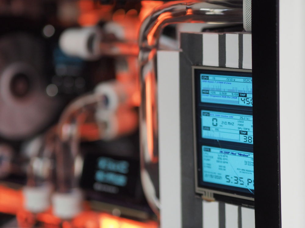
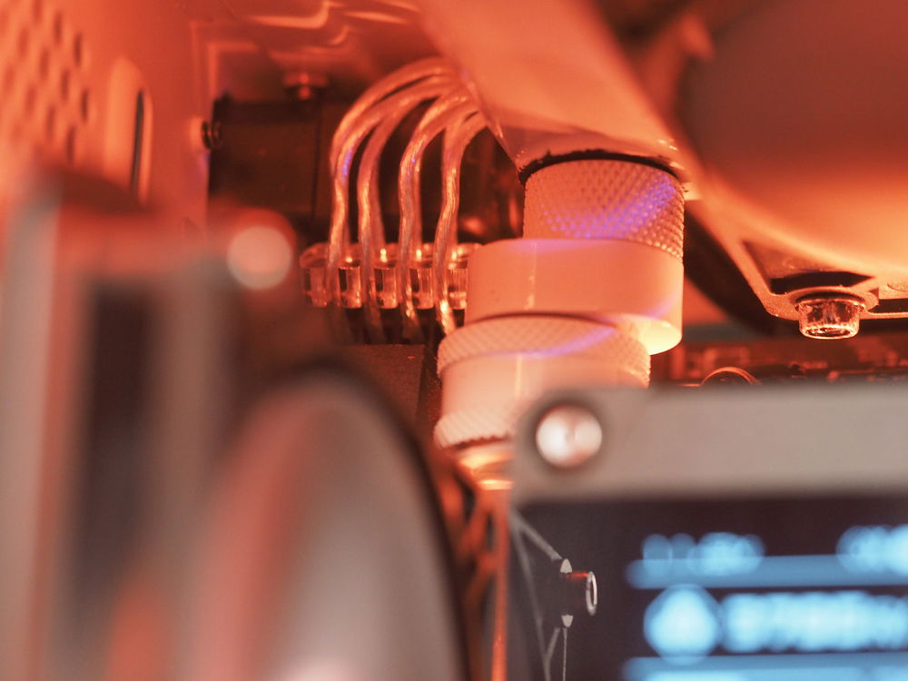
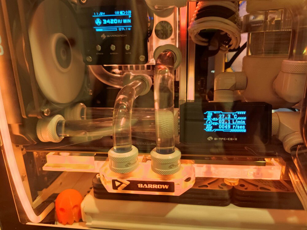
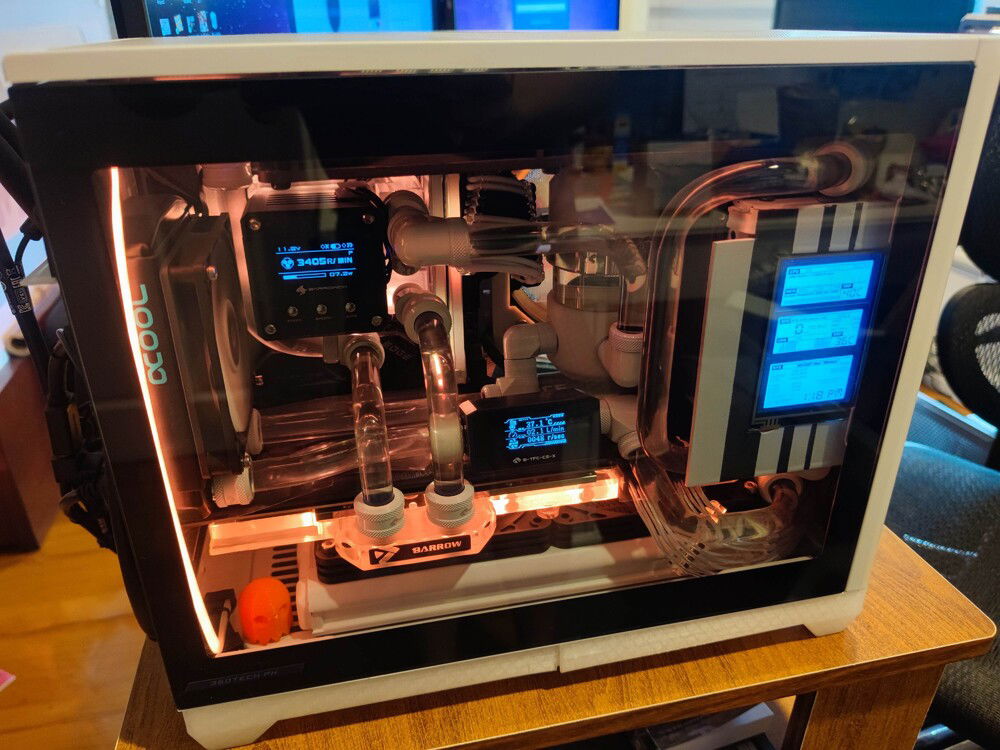
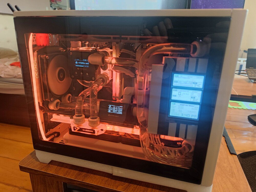
Sensor Panel
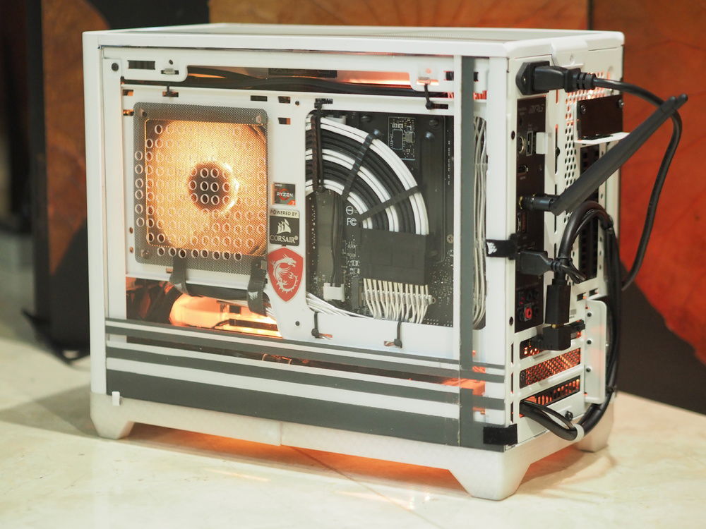
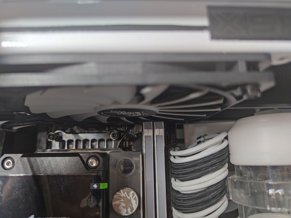
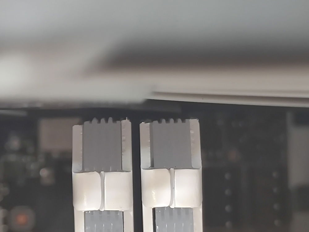
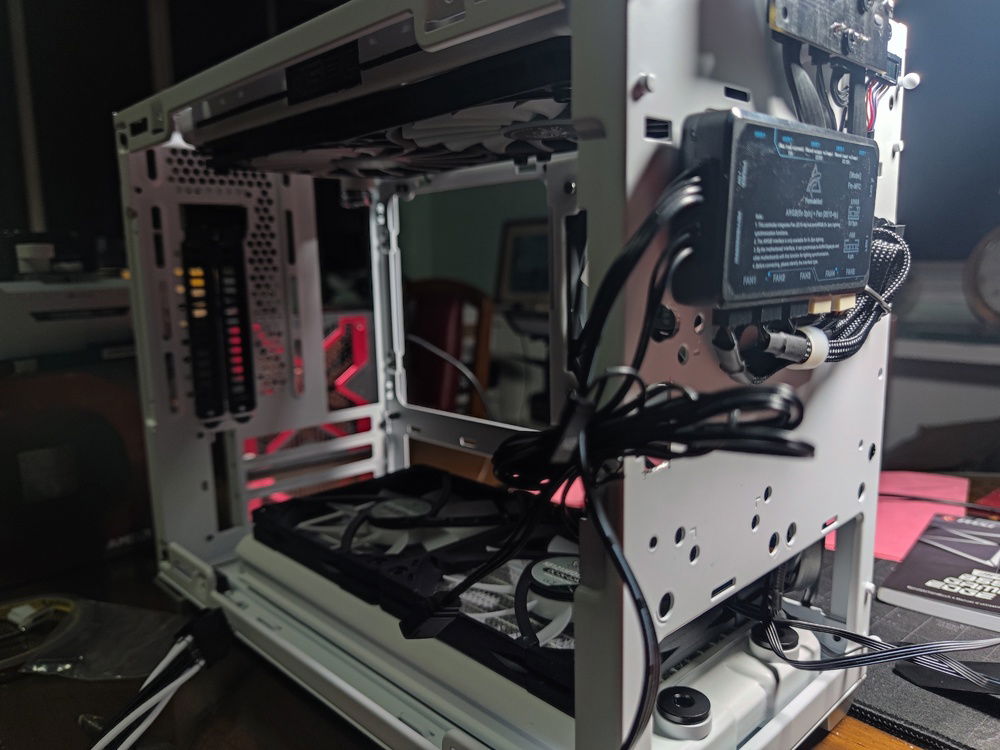
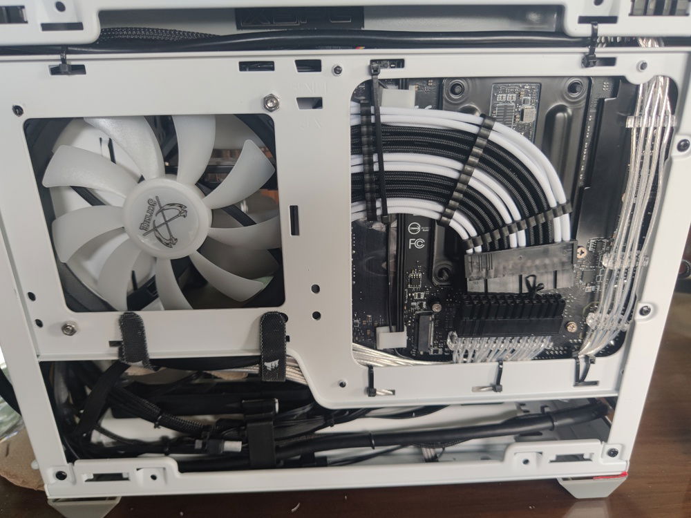
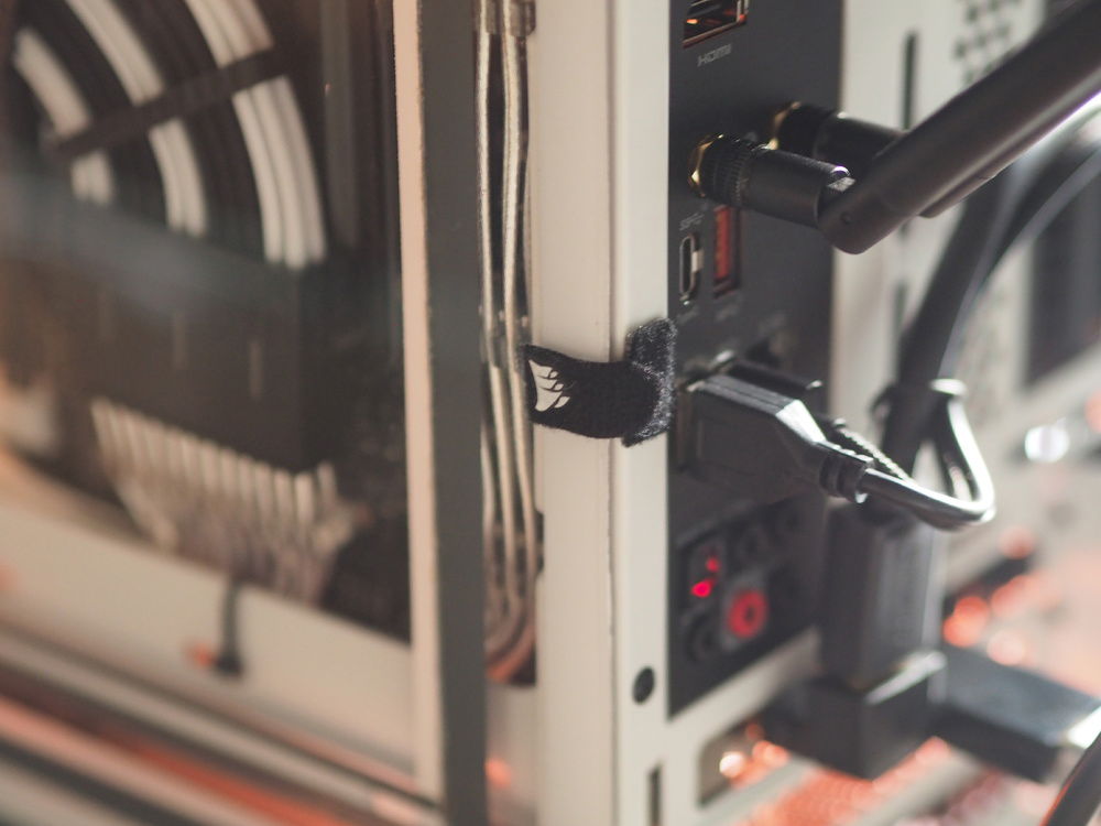
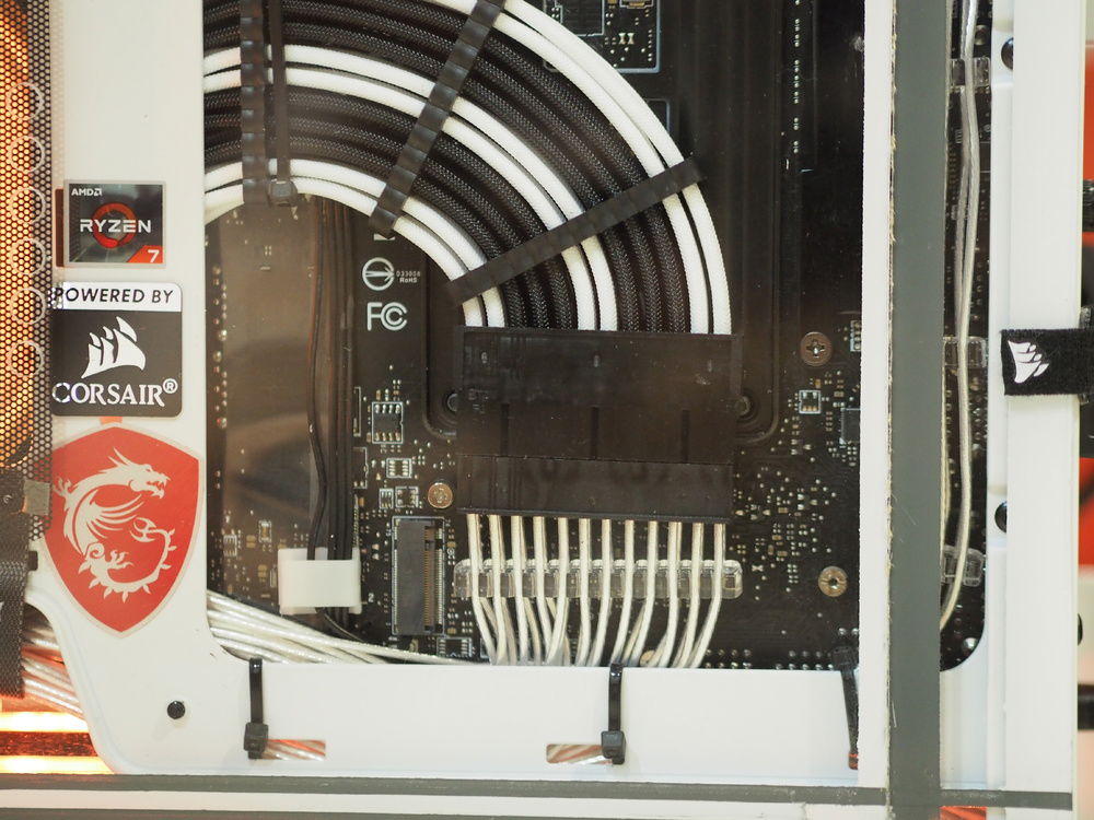
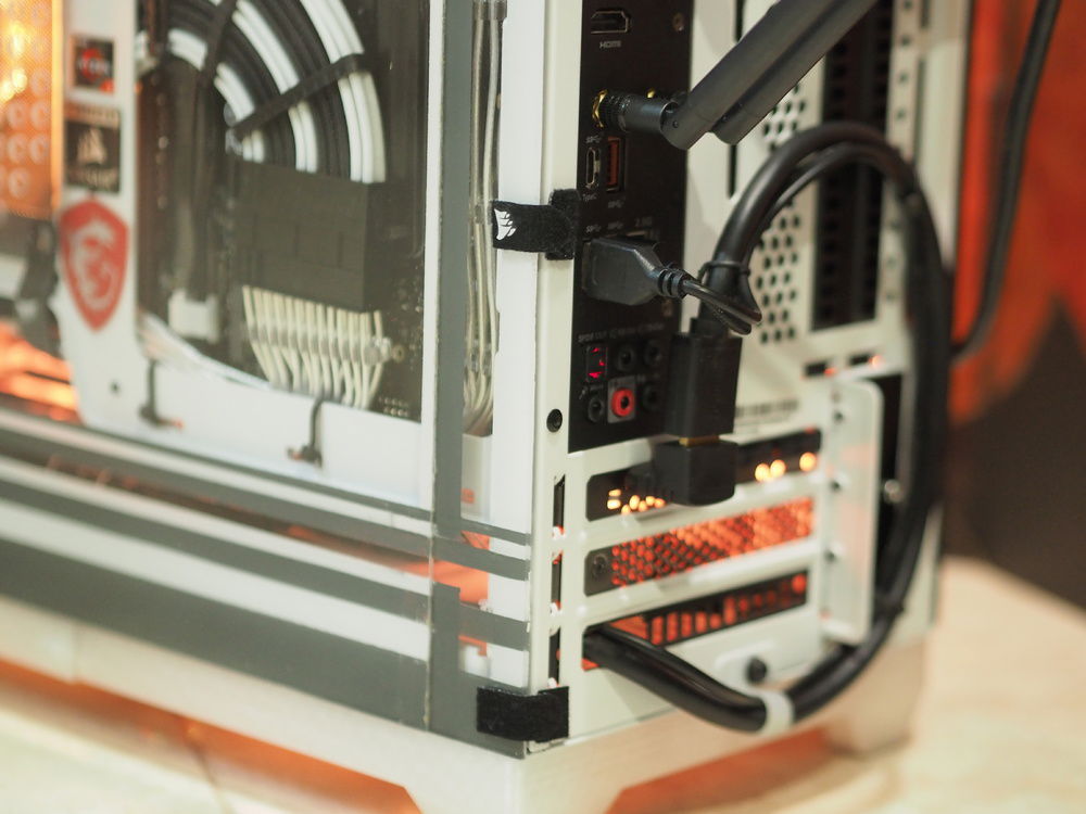
Rear of motherboard cable display

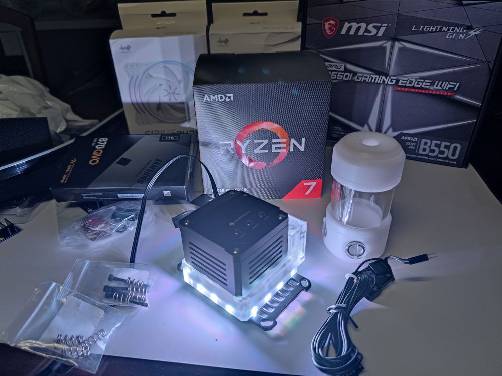
As with most builds, my parts came in slowly, over 2 months. It gave me time to plan out the build and the general theme.
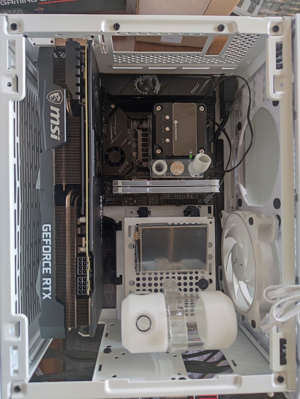
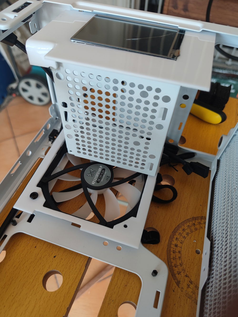
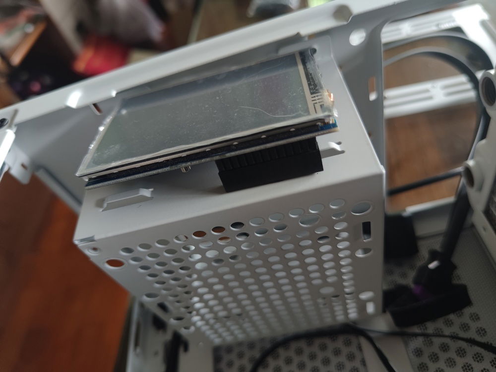
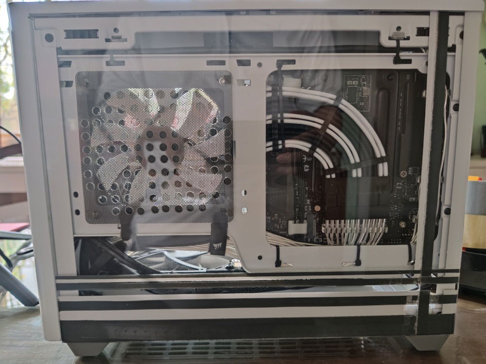
The NR200P supports 2 locations for the SFX power supply, and I was choosing between the two. I ultimately found that the side placement of the PSU cage took up too much space and placed the internal LCD too far away from the glass side panel.
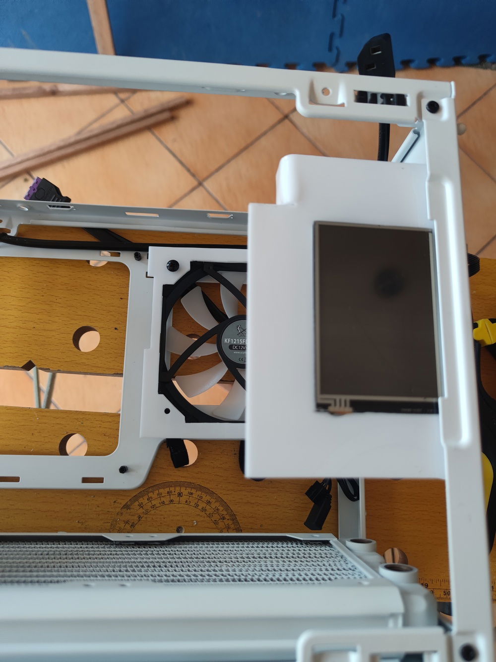
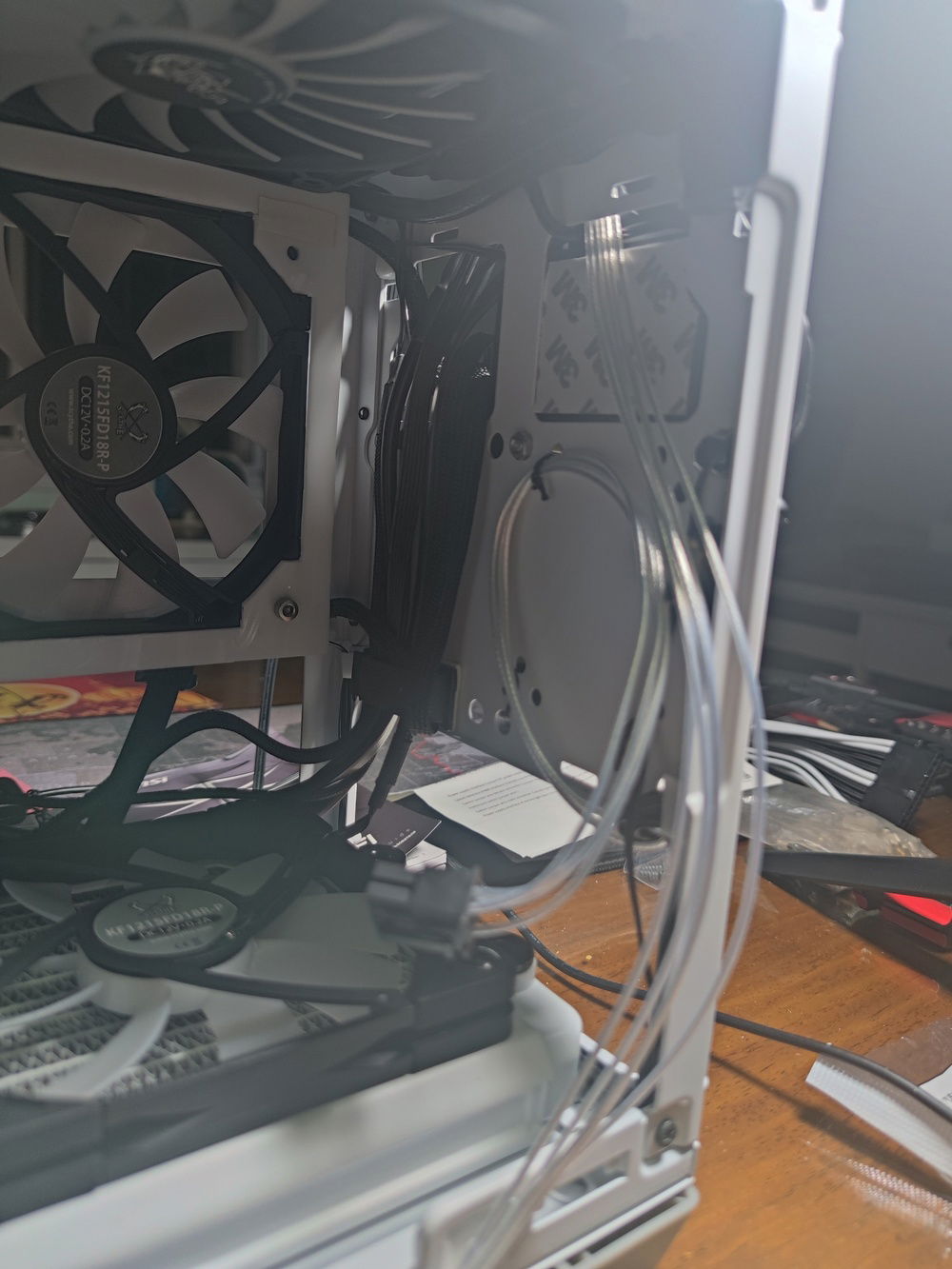
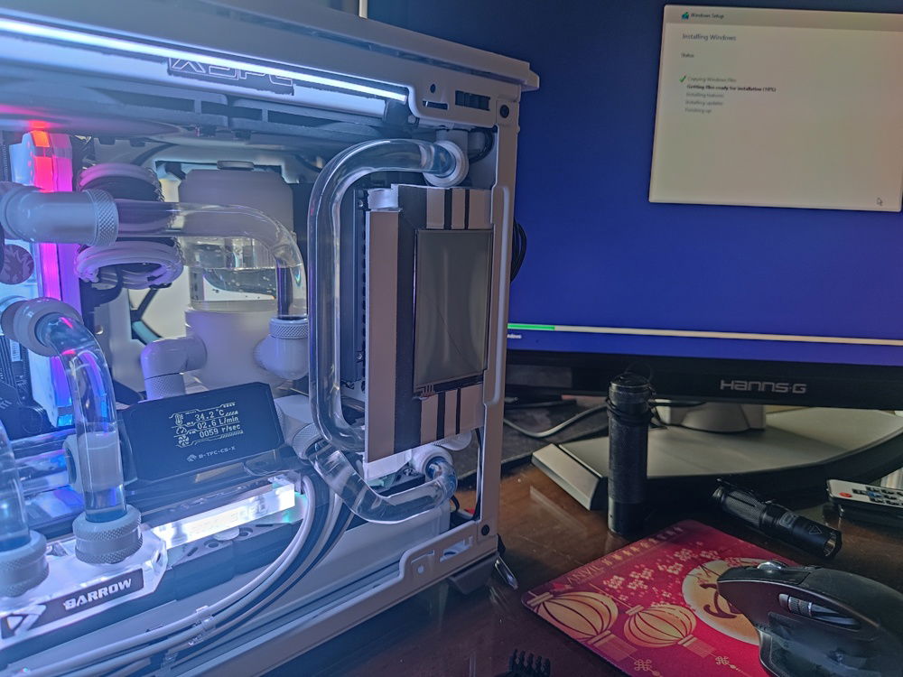
This was the configuration I ultimately went with, with the LCD clase to the clear glass panel and the PSU out of the way and enabling the placing of an additional intake fan on the side; a 17mm thick Scythe Flex 120mm fan.
This was before I figured out how I was going to mount the top rad; test fitting dual top exhausts with 25mm thick fans gave me enough warning to anticipate serious clearance issues for the radiator and fan combo I wanted to install. The side fan intake and the internal LCD is also mocked up in this pic.
I installed my water block as soon as it arrived and tested the fitment again; as planned, it gave just enough space to fit the bottom radiator fans with just enough of a gap to be practical, airflow-wise.
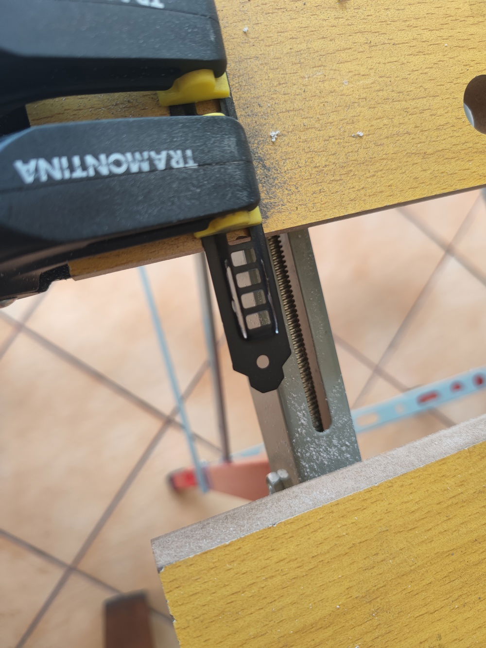
Part of the modding involved the tedious cutting of screws down to length due to the thin components I was working with.
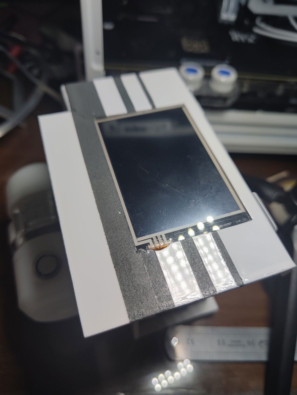
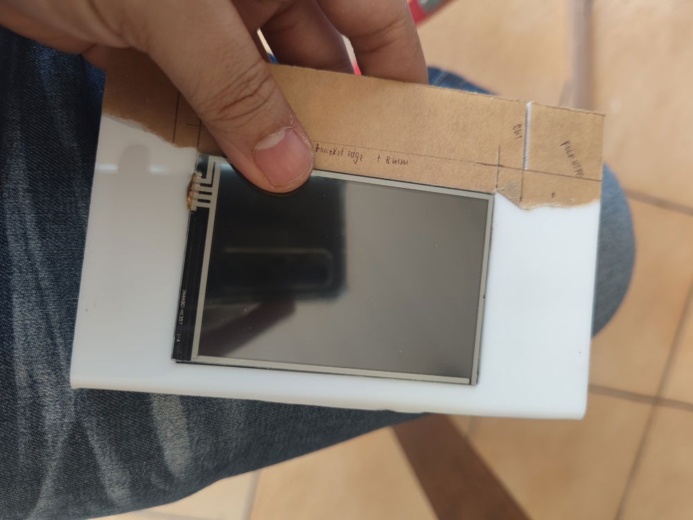
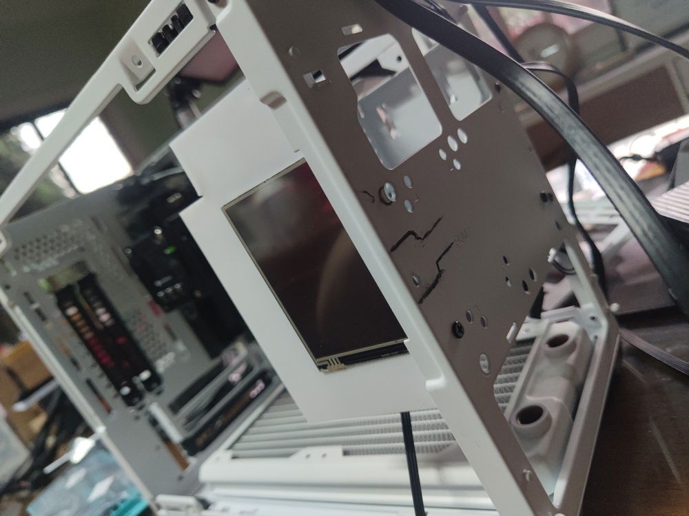
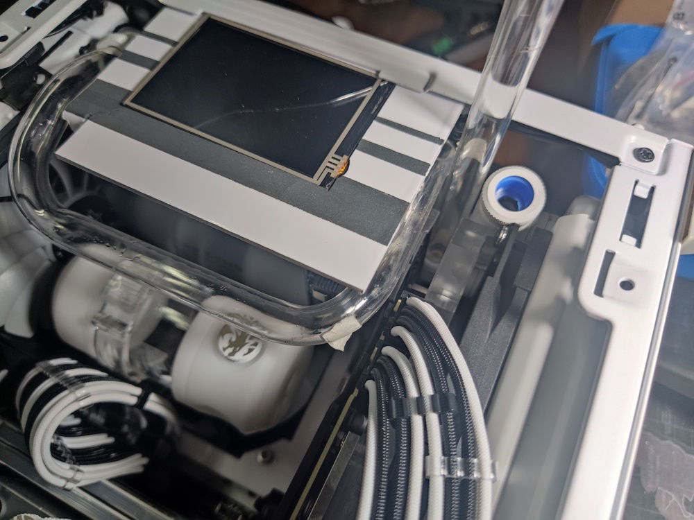
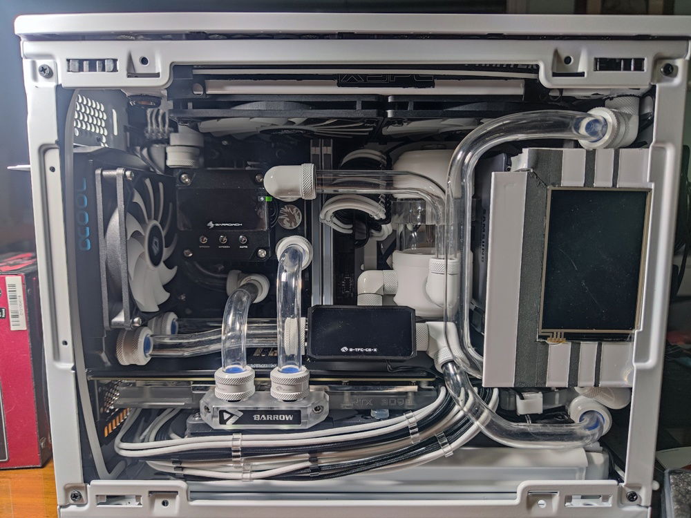
The finished product. I made sure to clear the touch screen interface cables at the bottom left of the screen.
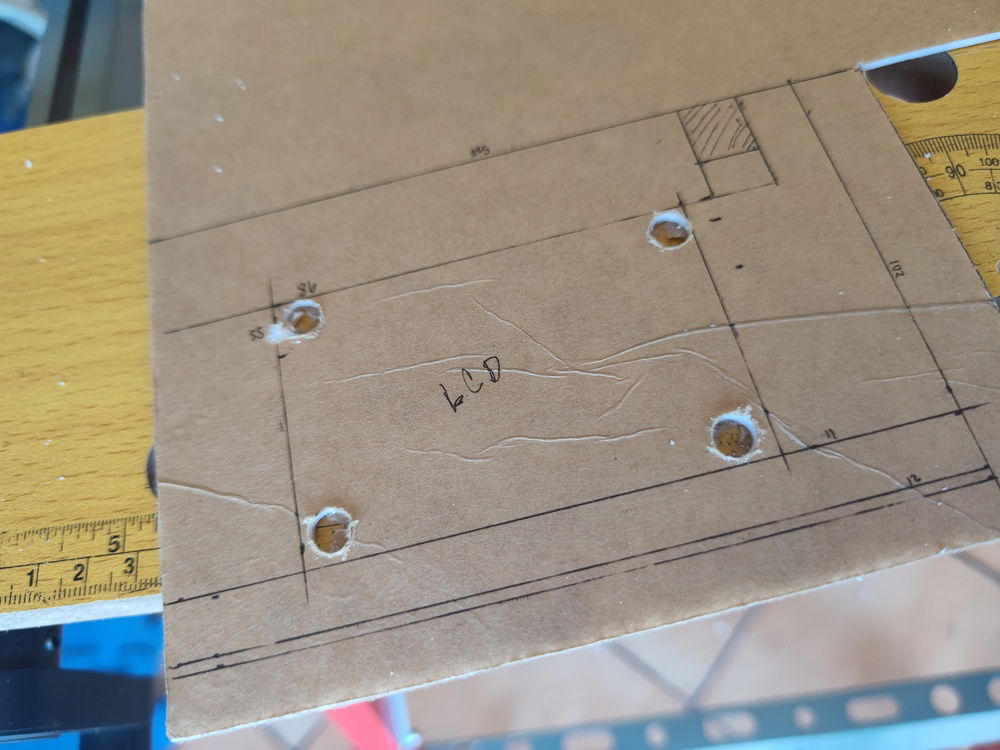
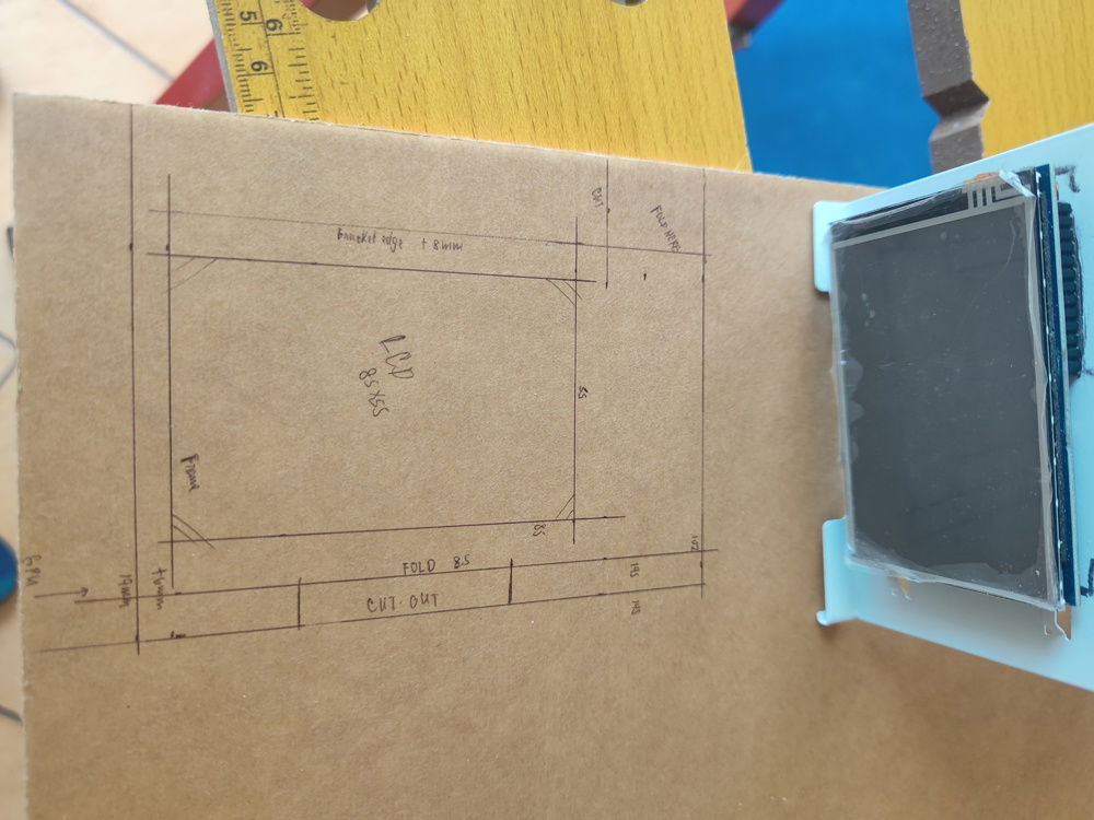
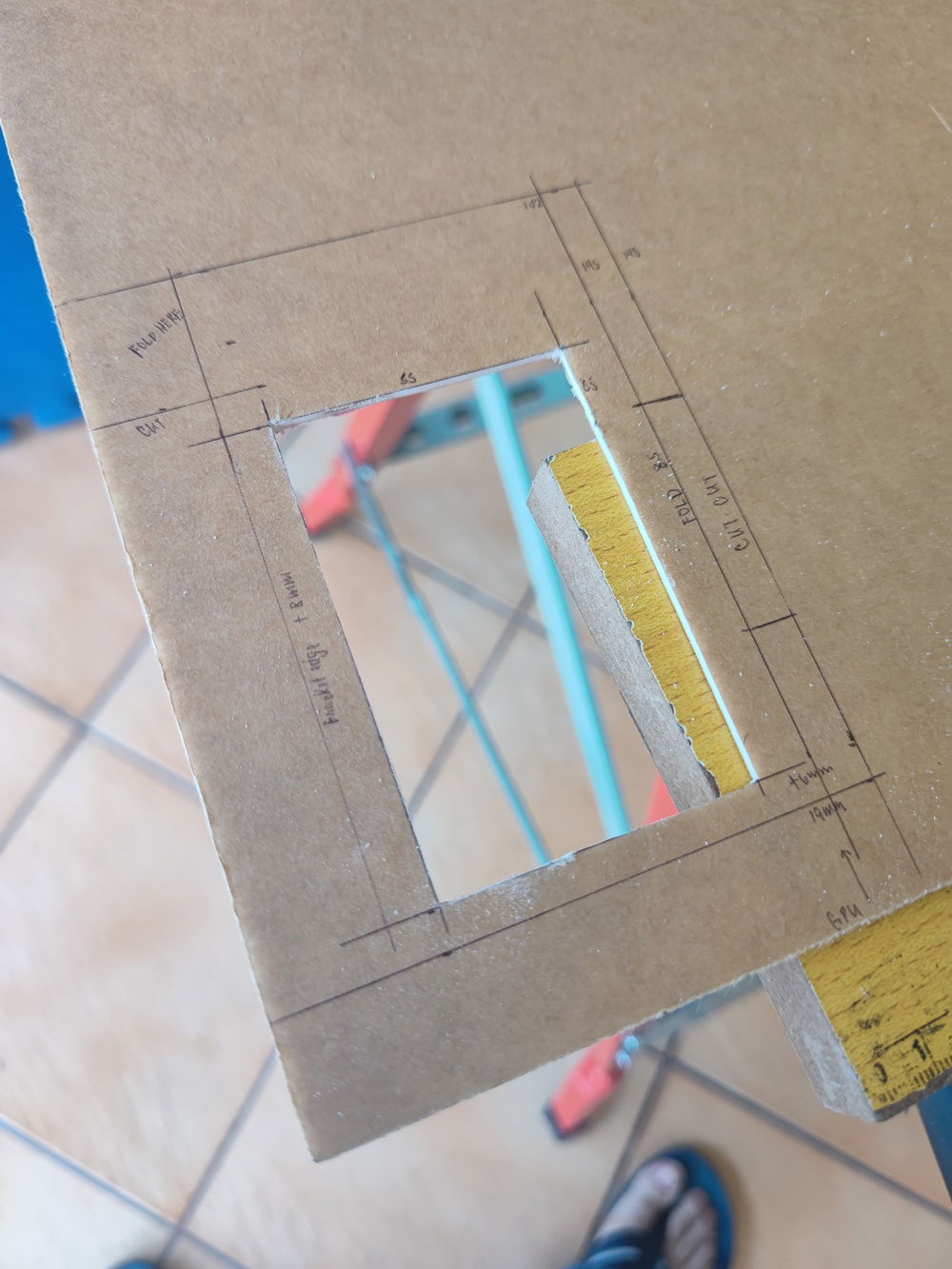
To have the cleanest routing for the LCD panle cables, I decided to place it near the side panel glass, on the PSU cage. That meant I had to cut access holes into the front panel of the case and mount the LCD onto the PSU cage somehow.
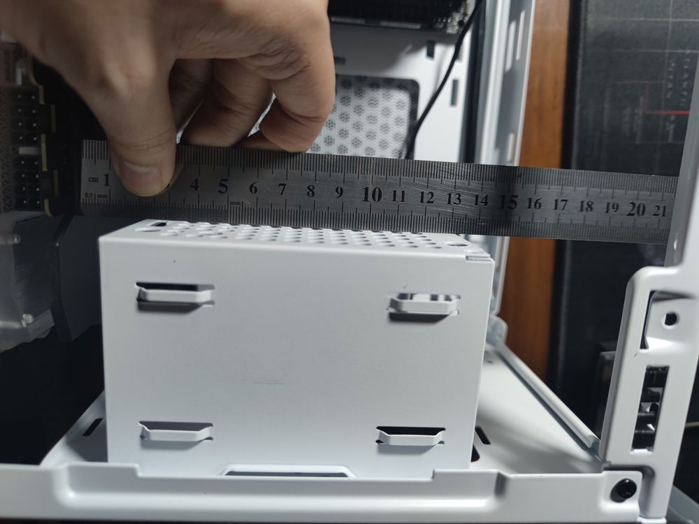
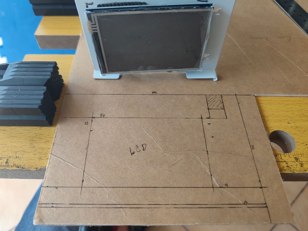
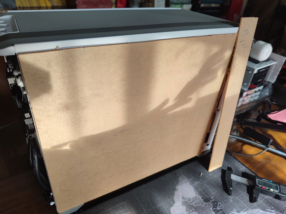
Measuring out the PSU cage dimensions so I could decide on the shroud size and LCD placement.
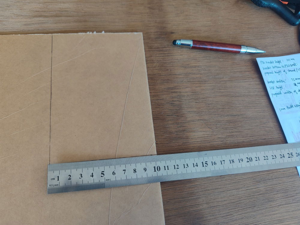
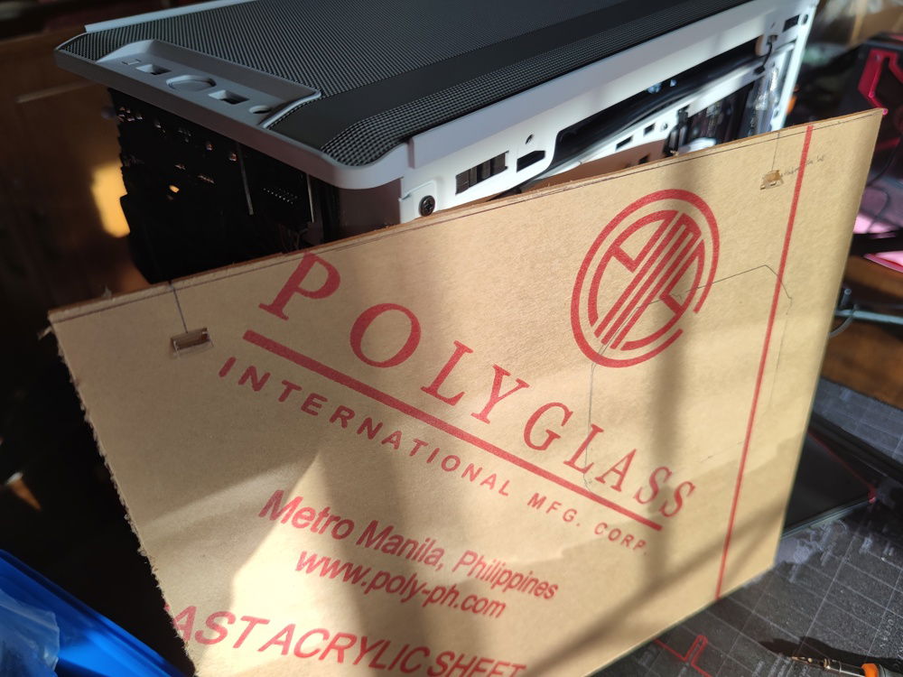
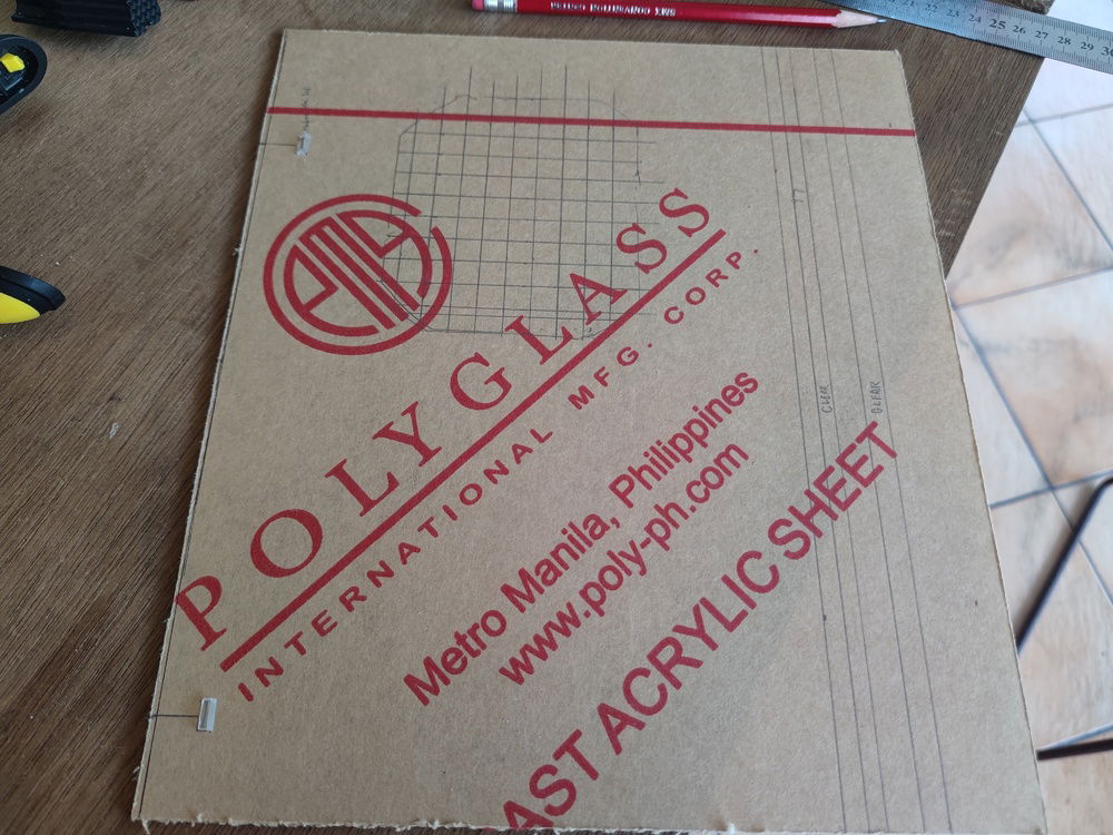
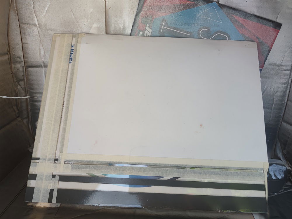
Initial measurements for the white acrylic I would be using.
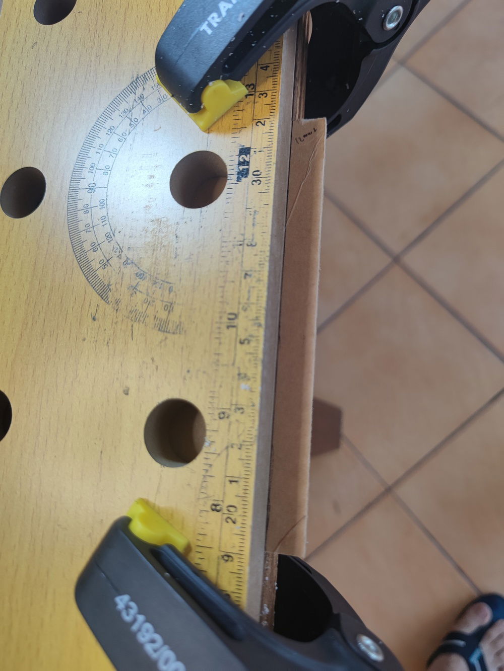
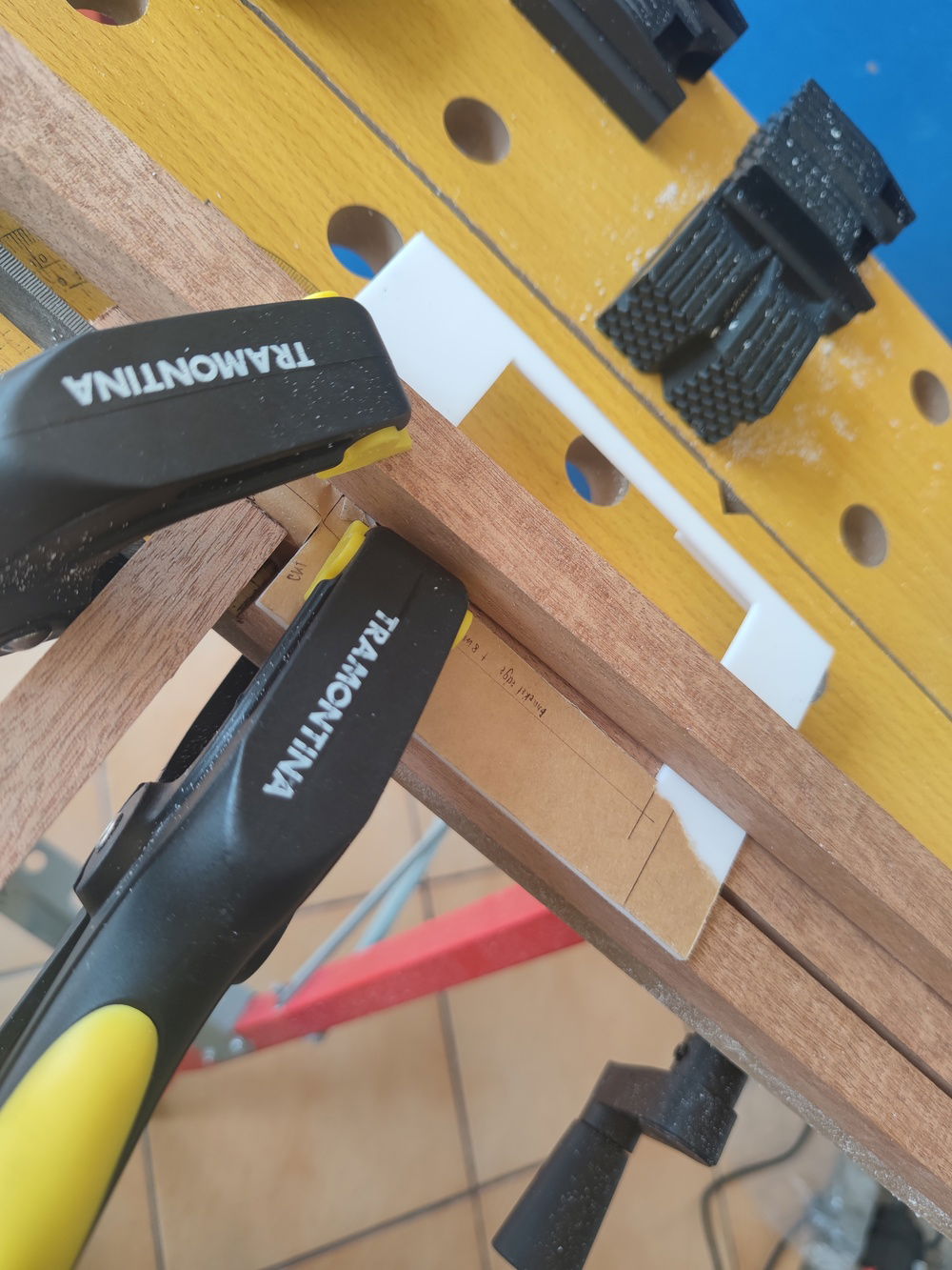
Bending the acrylic turned out to be easier than expected; but the problem became one of positioning and lining up the screw holes. Overheating was a real concern as well.
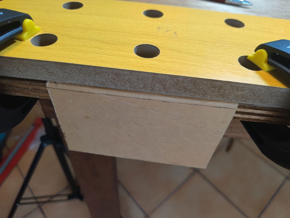
First try was successful, but it turned out I needed to cut away a lot of material for the shroud to fit properly.
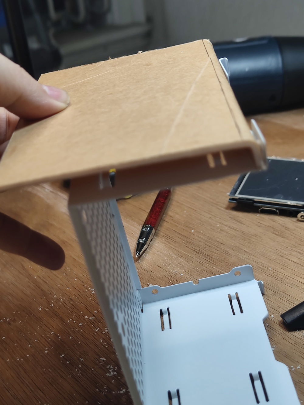
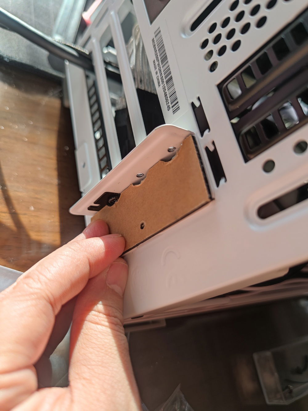
The fold in the acrylic was designed to become an anchor point when I screwed the whole PSU cage assembly onto the front of the case. One screw would hold both the cage and the shroud while creating space for the thickness of the LCD.
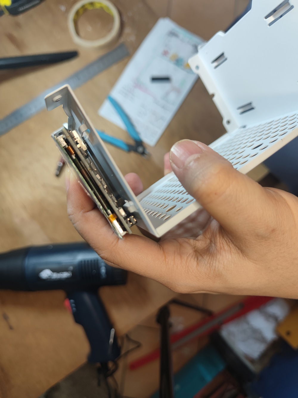
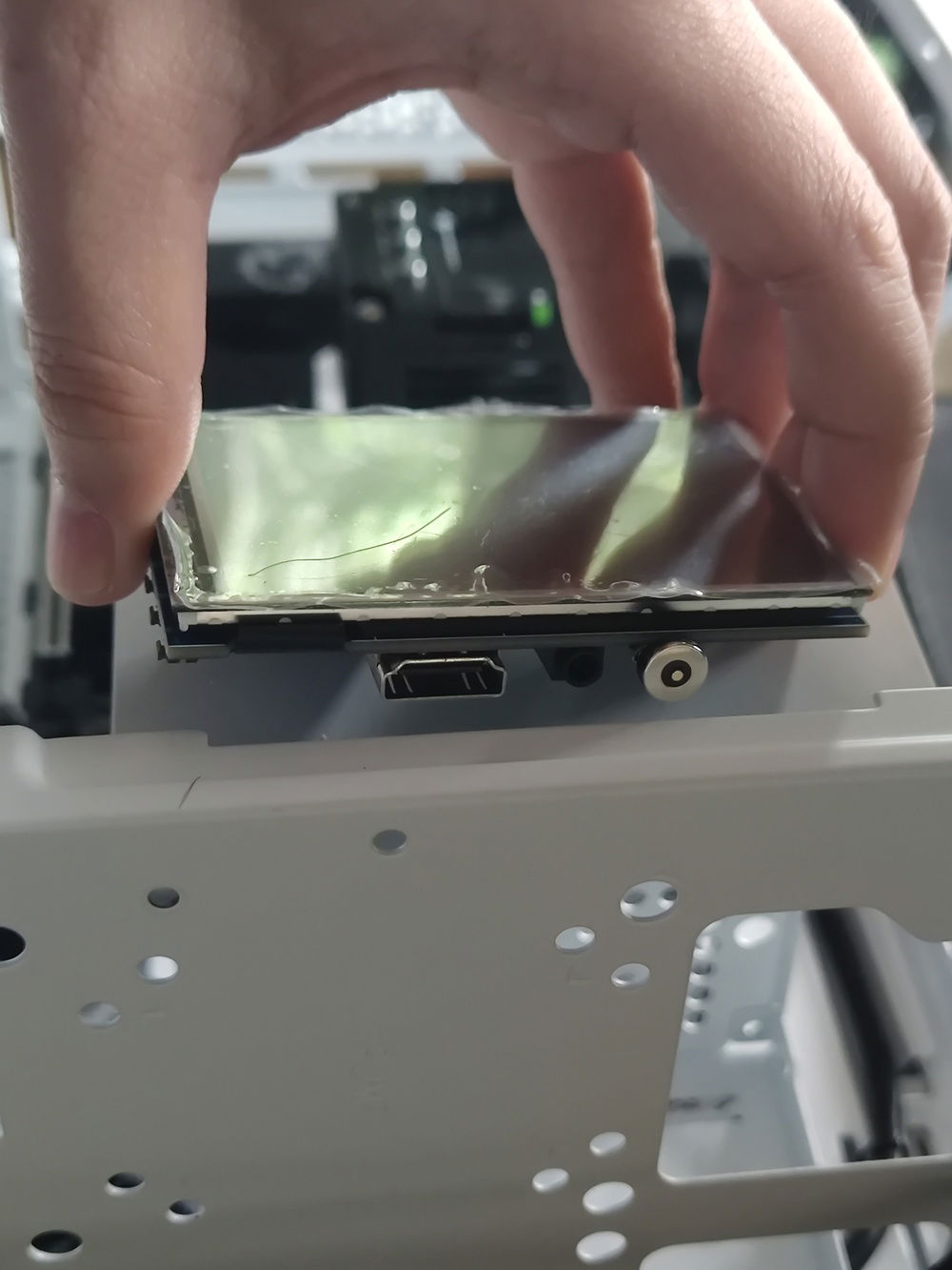
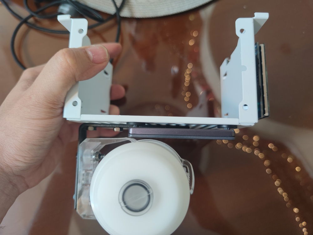
Determining the thickness of the LCD after removing the GPIO pins.
Preliminary measurement for HDMI cable placement.
I first drilled into the corners of the acrylic so I could fit the jigsaw blade and cut out the 3.5" hole. I ultimately cracked the side of the frame and had to start over.
Cutting the LCD frame; the first attempt of four.
This was the 3rd attempt. (Which still failed - this time due to over heating the acrylic trying to correct a wrong measurement.)
3rd time's the charm? Nope.
I eventually made the acrylic bending after the cutting to simplify the process; I also found the best heat level and duration to be able to reheat the piece without overheating it.
4th try proved to be the one I ended up with.
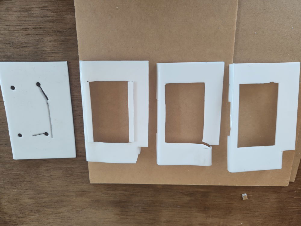
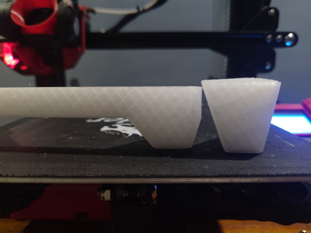
The piece to the rightmost of the picture is the one I used in the build. It's really a learning process.
The LCD was mounted using 3M mounting tape and eventually, the frame that surrounds it.
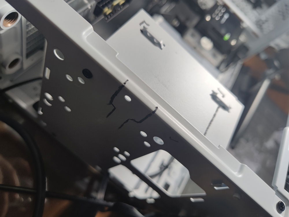
I had to cut away some PSU cage material fo the cables to have a clean shot through the side and past the front metal access holes.
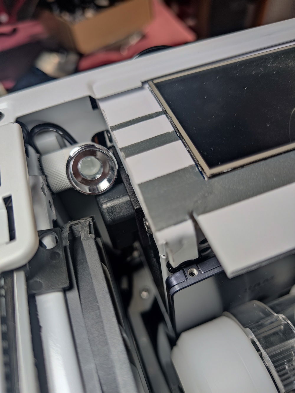
The other side of the LCD is propped up using rubber mounts to keep the LCD level.
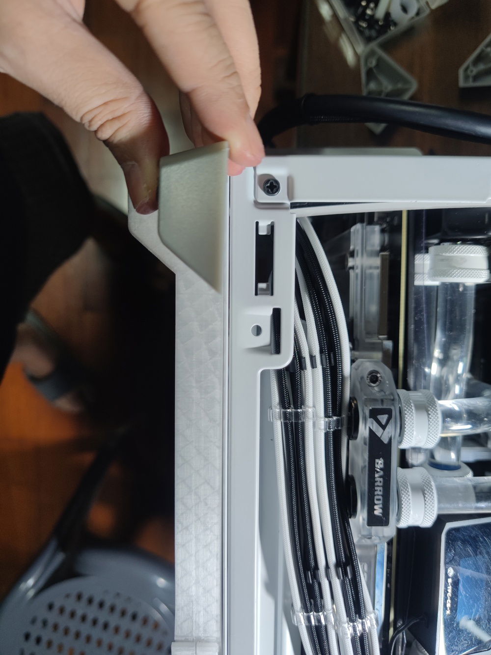
This pic shows that the shroud is not fully level with the LCD; this was fixed later byscrewing in the tab at upper left.
Front view of the shroud
I would end up cutting off a big portion of the top of the shroud to fit my tubing, but otherwise the shroud served its purpose of hiding the PSU cage and the LCD PCB.
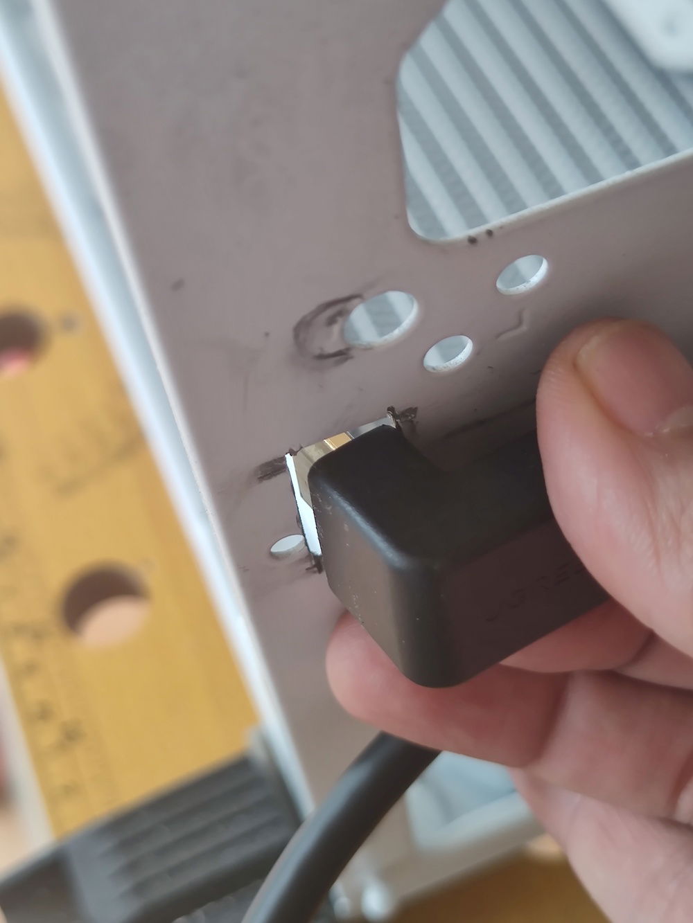
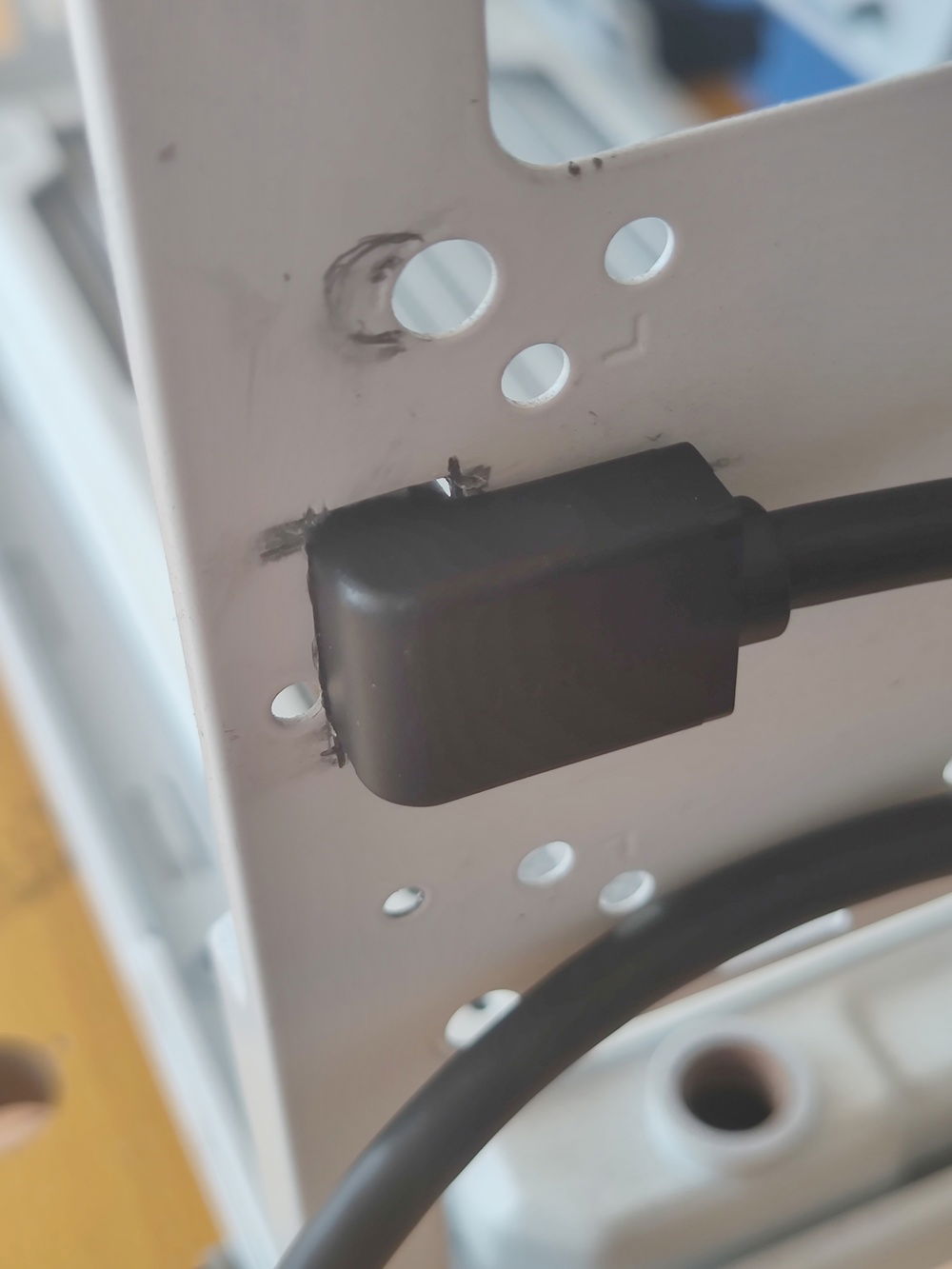
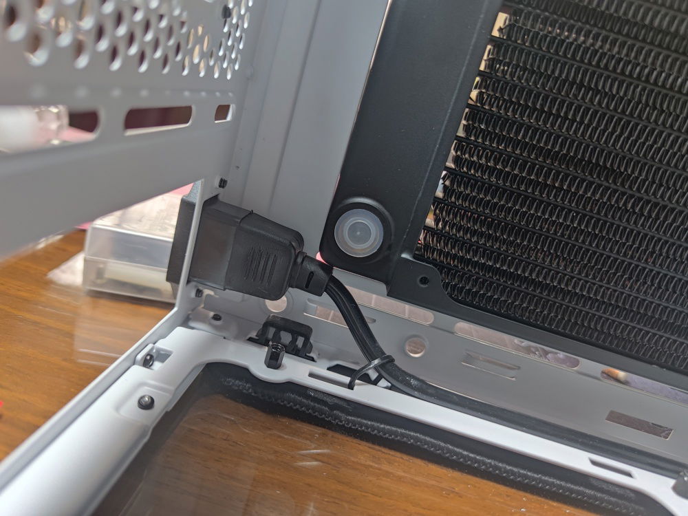
Hiding and routing the HDMI and USB cables through the front of the enclosure.
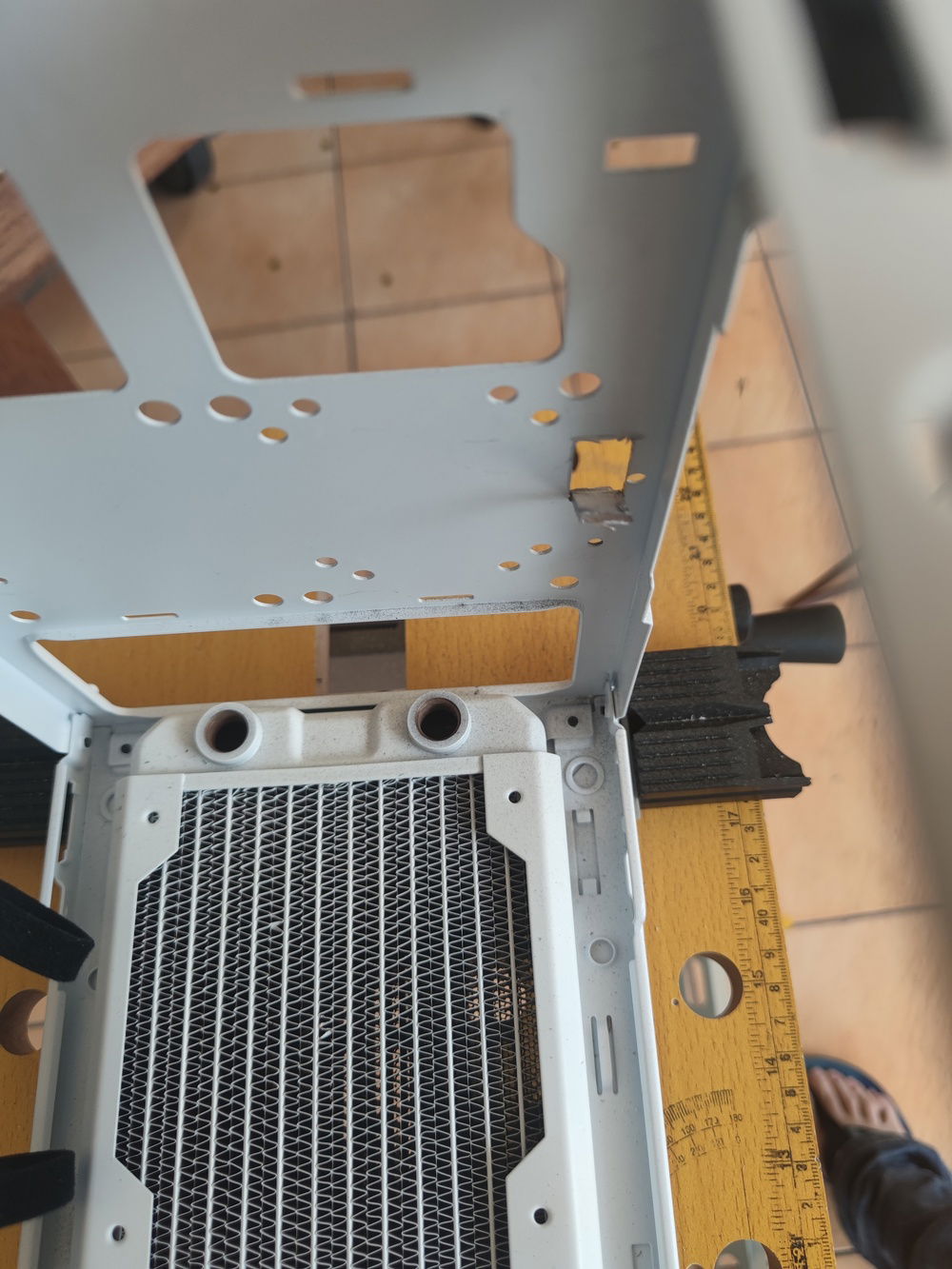
Cooler Master uses some tough steel for its cases. I used a dremel tool to cut open this access port for the HDMI.
Three coats of white and gray was used to finish the shroud/frame.
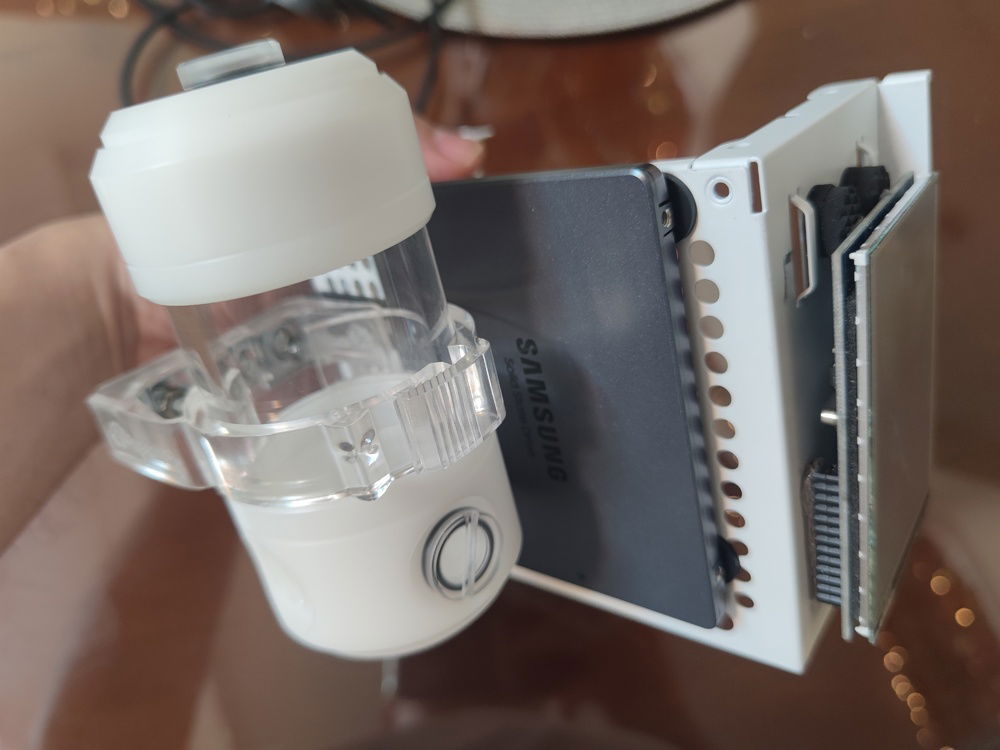
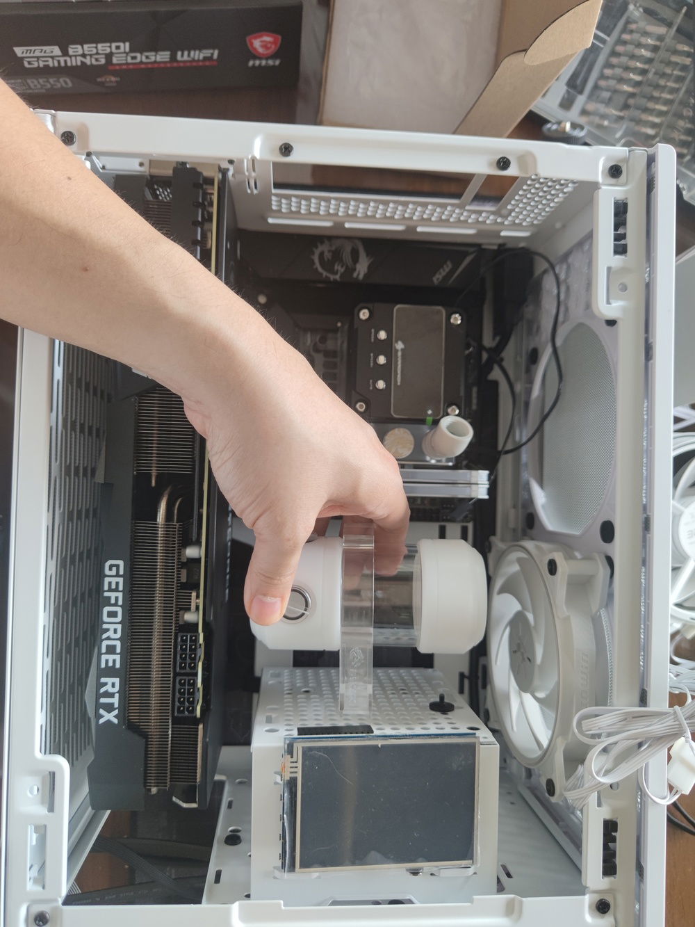
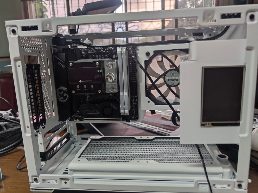
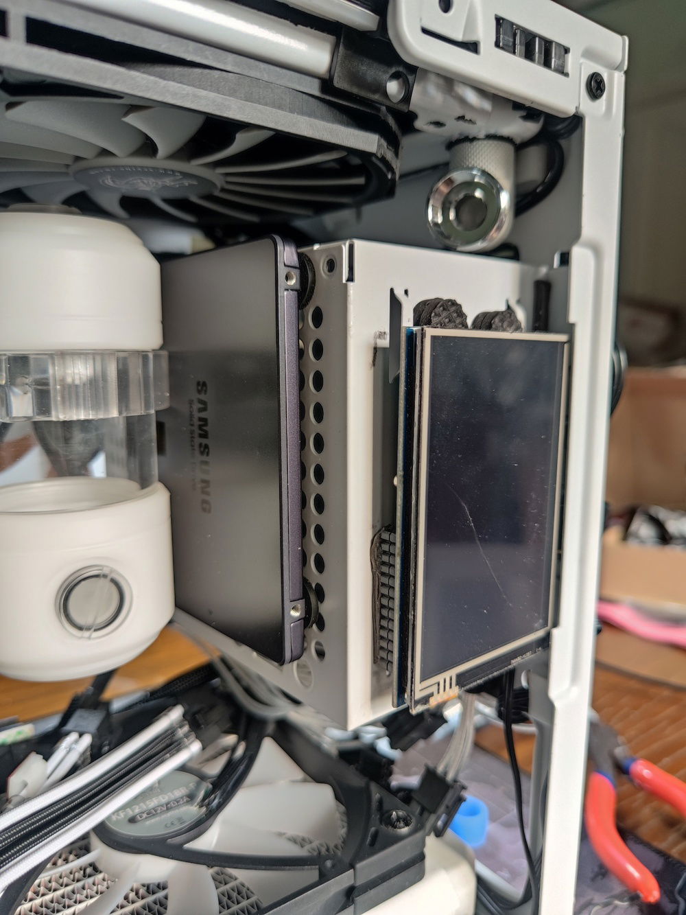
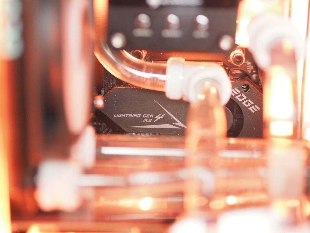
I decided to mount the SSD to the PSU cage to save space (also because all of the wiring is hidden in the front section of the enclosure, taking up the existing front mounts for SSDs). The sideway mount for the reservoir is required to clear the motherboard ATX power cables and create more room for airflow from the side mounted intake fan.
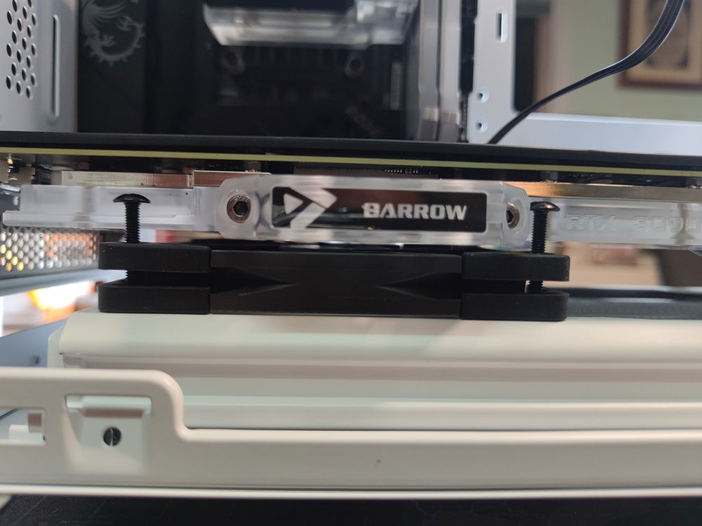
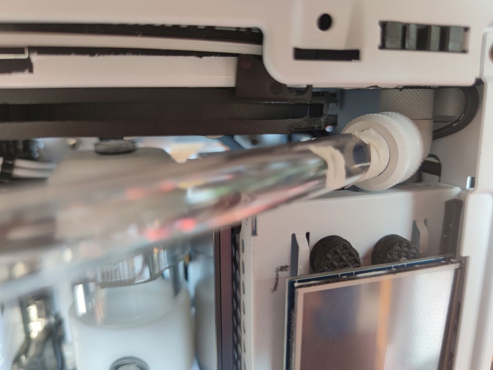
I have barely half a millimeter of clearance between SSD and reservoir. Not that I have to worry about vibration with a non mechanical storage device.
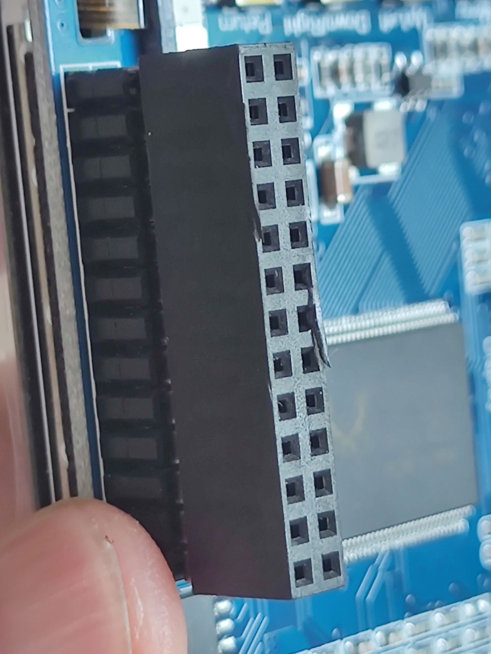
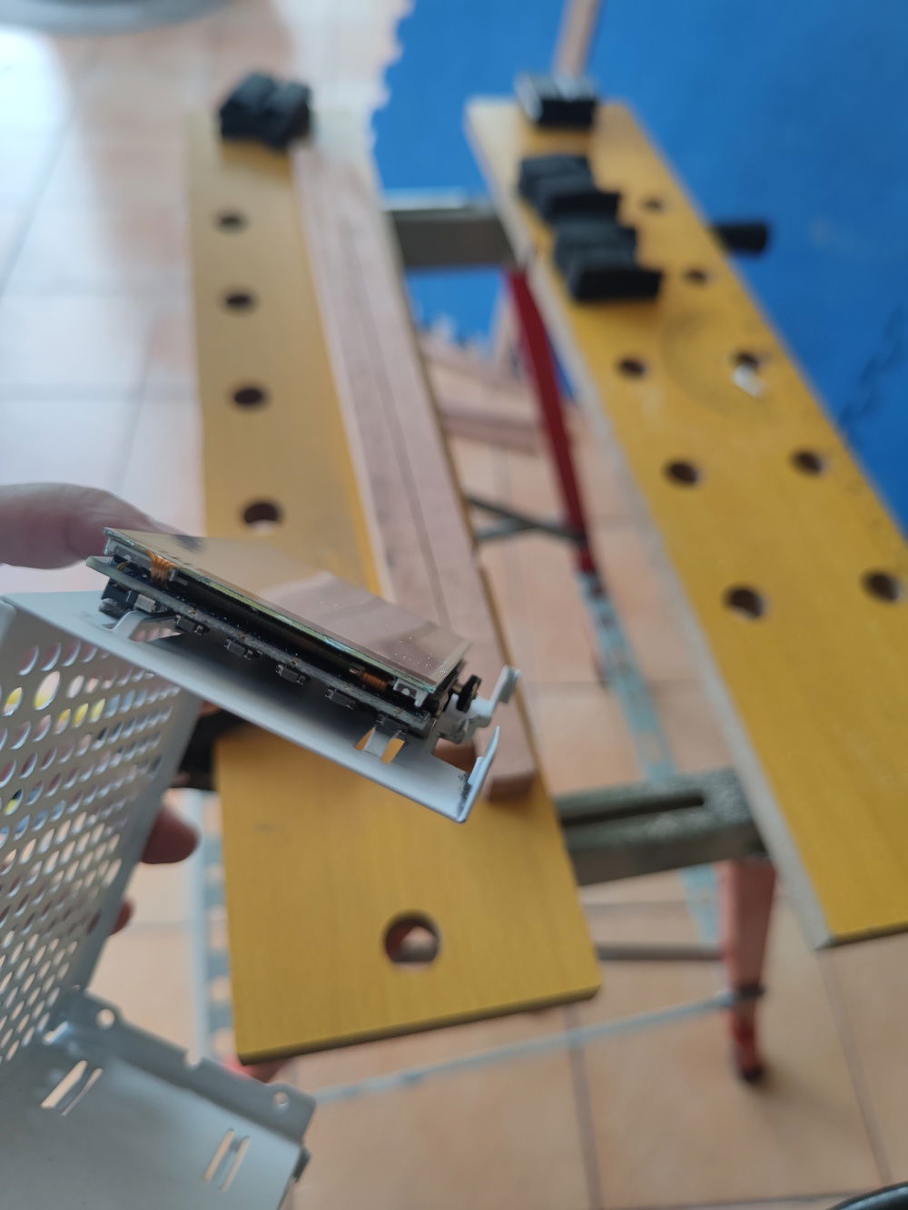
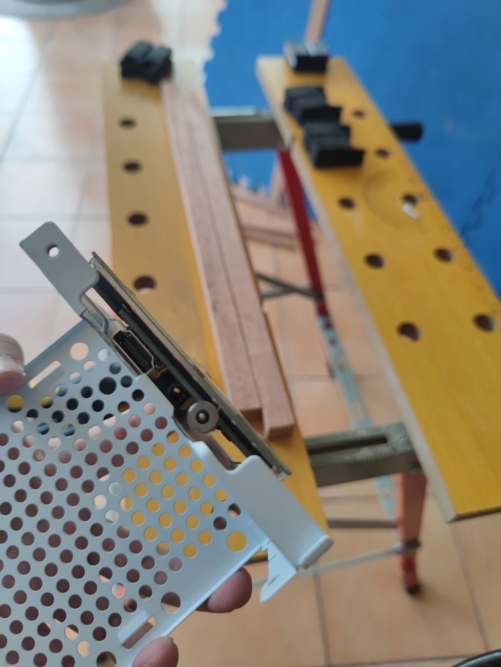
I got a 3.5" LCD for a Raspberry Pi that connected to the Pi using GPIO connectors; I had to cut these pins for the screen to fit flush (and fit under the tempered glass side panel as well).
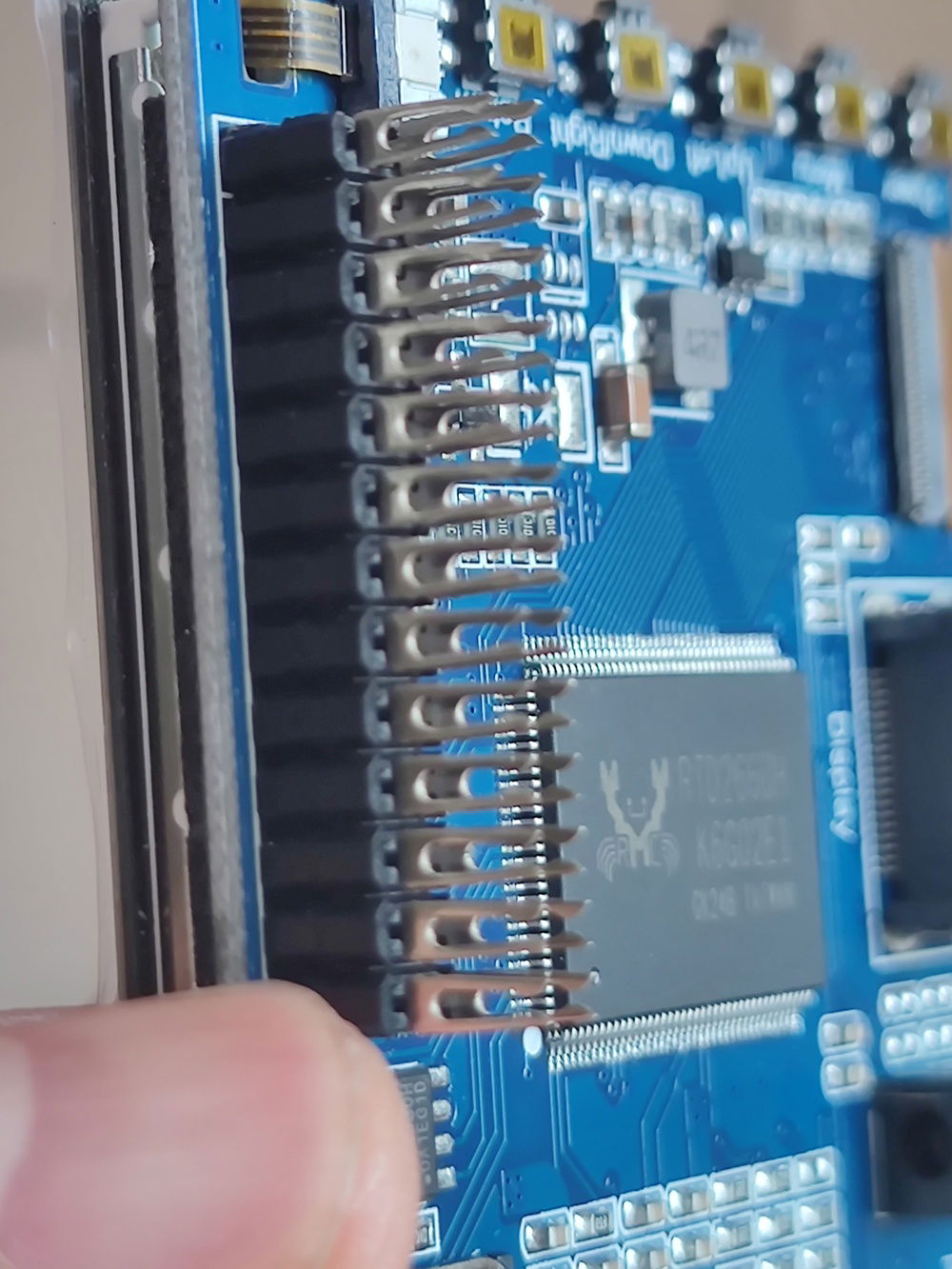
Cutting the pins was easy but a bit painful; I always tried to avoid defacing hardware as much as possible. In this case, it was unavoidable.
The pins had to go.
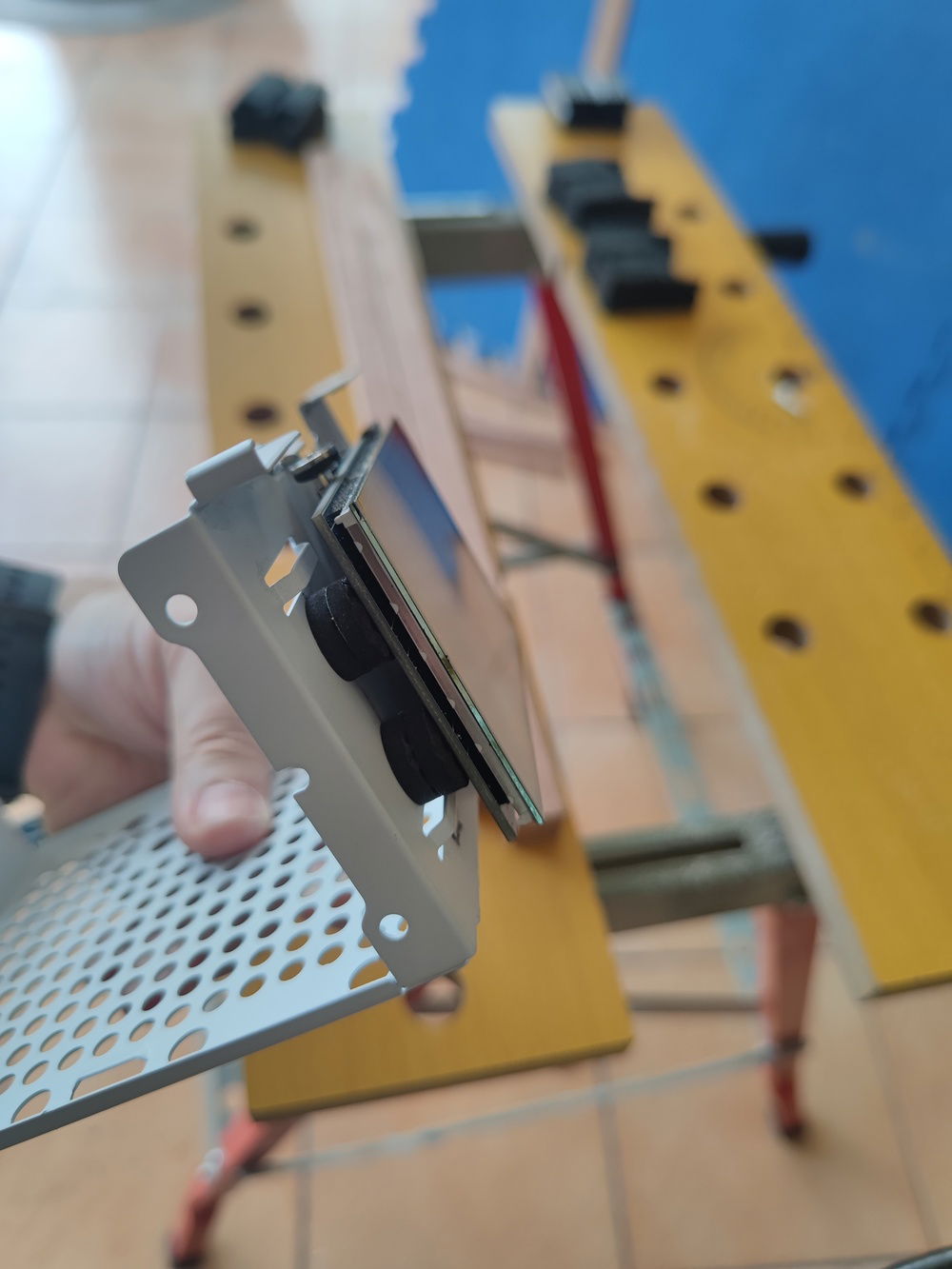
There was not enough clearance for me to use the included anti-vibration pads.
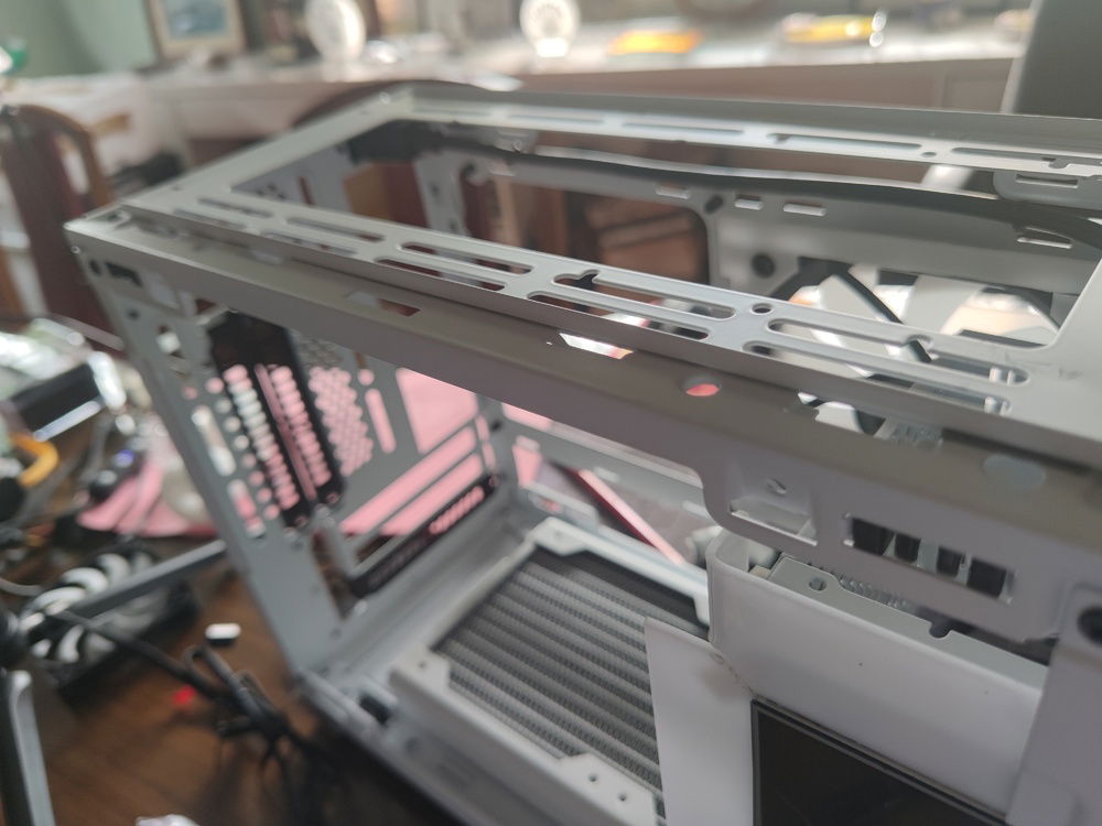
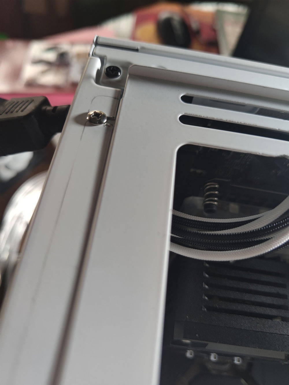
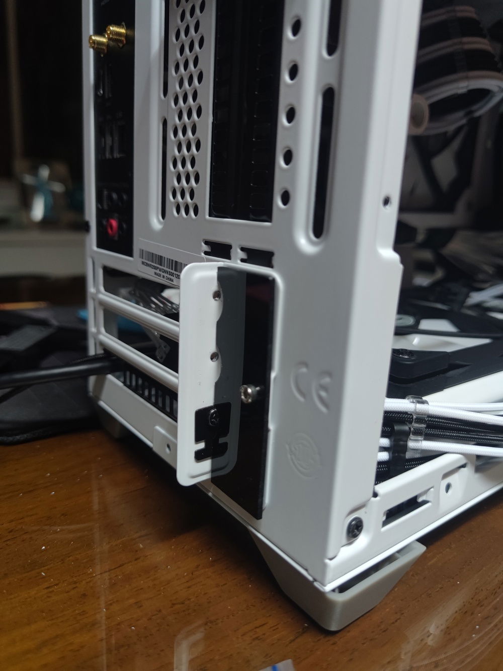
My first idea was to mount the side bracket with the edges down, to clear the metal on the front of the case and avoid having to cut or interfere with the plastic top panel, with the hope that I could still fit some fans on top, or change the configuration in the future.
As seen in the picture, this position gave me a level mounting bracket for the top, with less difficulty for locating the holes for the screws.
..and measuring it out wasn't very reassuring.

Test mounting the slim radiator revealed another potential problem - clearance for the tubing would be almost impossible. My first idea of routing to the side of the PSU cage, past the LCD screen, would not work, so I would have to go around the cage. A problem for another day.
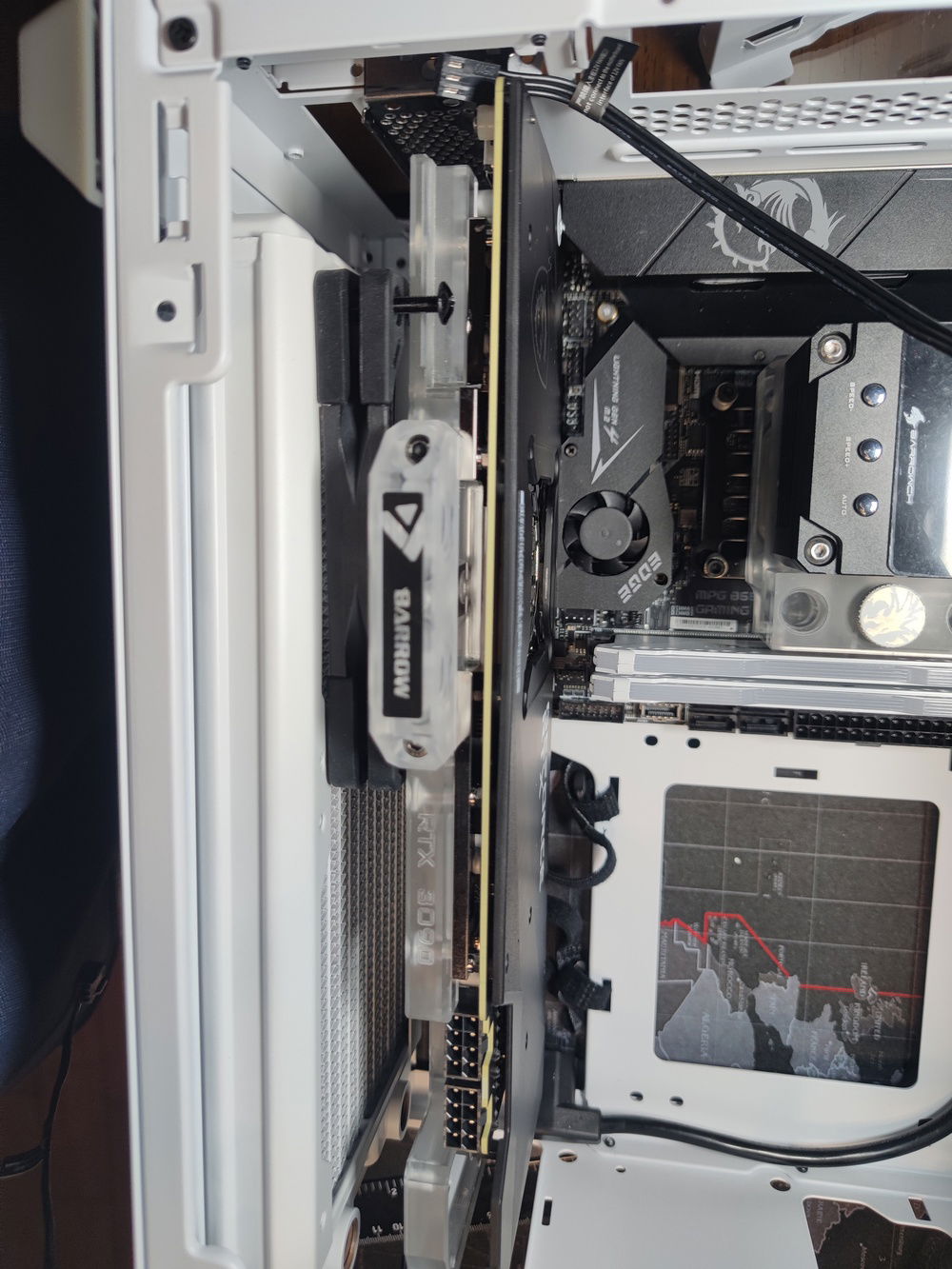
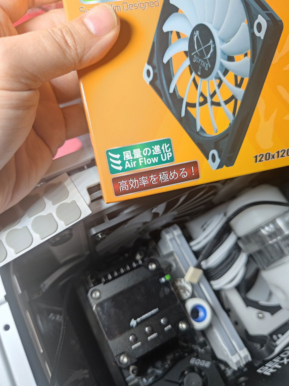
The fan on the elft of the pic are 17mm thick Scythe Kaze Flexes, which would not fit above the RAM. I could not test clearance until the Slims arrived. If those wouldn't fit, I would have to make it work some other way.
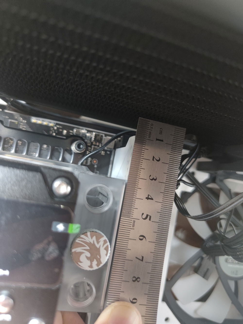
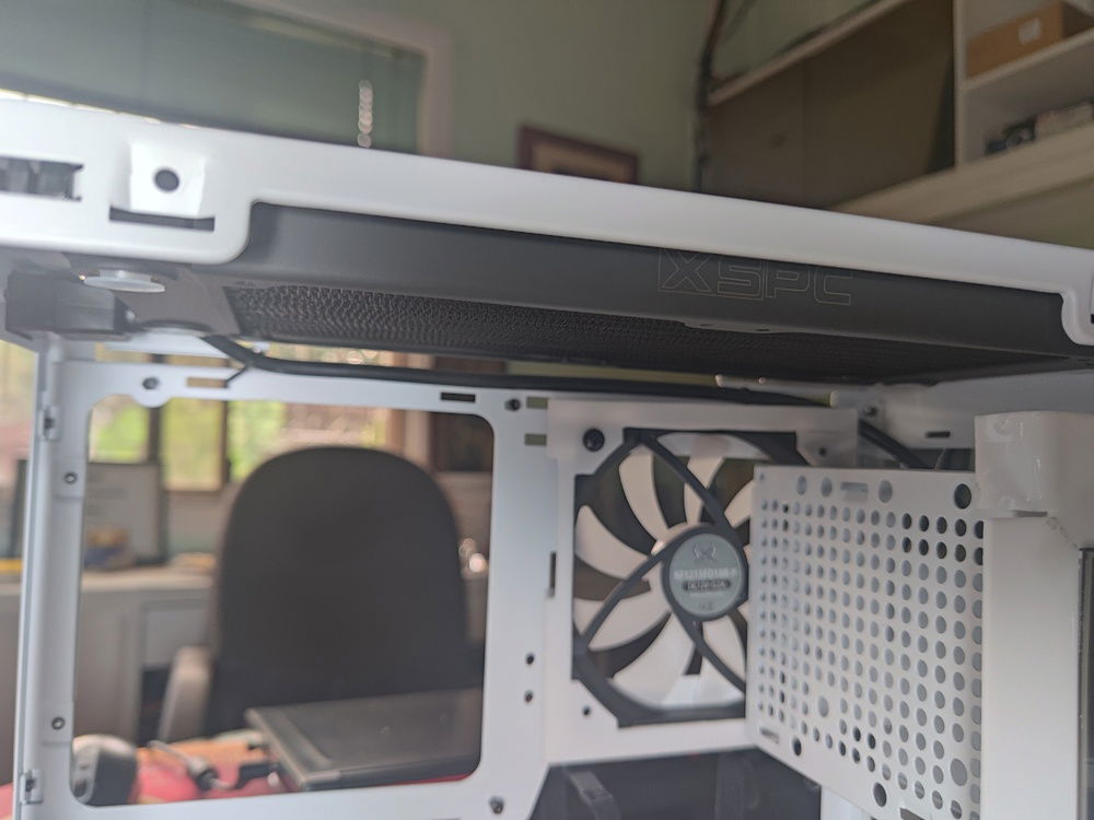
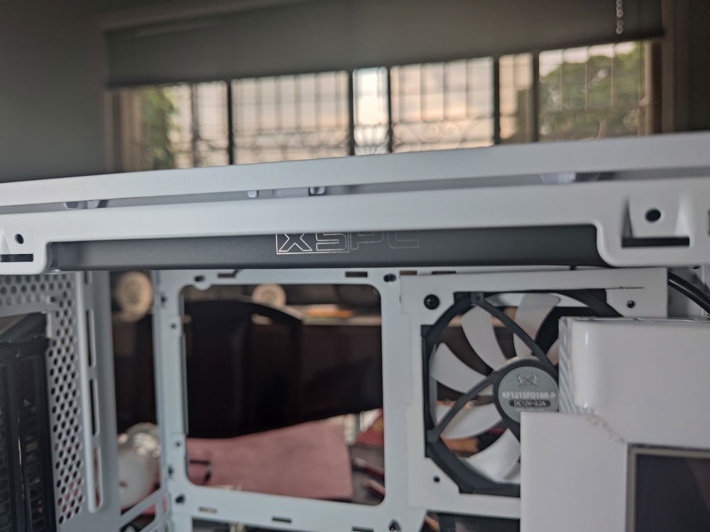
After my XSPC radiator arrived, a test fit proved it to be a good choice, at least width and length wise. Clearance to the RAM sticks remained to be seen.
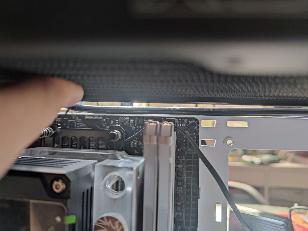
Eyeballing the clearance..
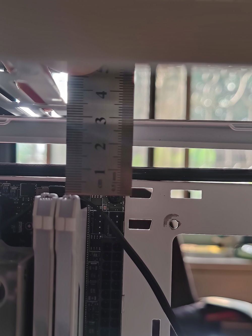
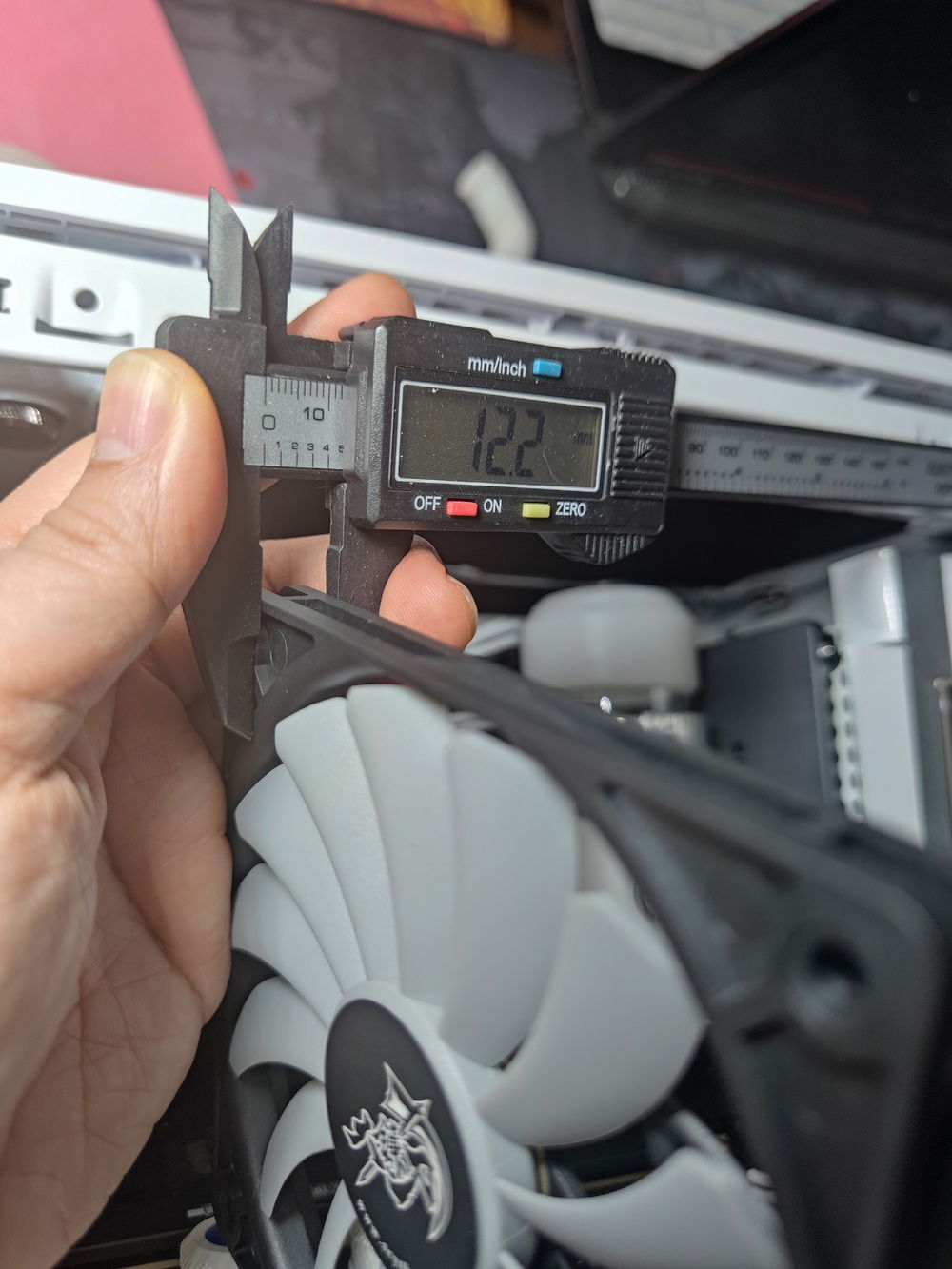
I estimated that I had around 34mm of clearance from RAM edge to the top bottom of the panel, which meant nothing else but an ultra slim radiator would work.
My choices were a 17mm chinese radiator I was unfamiliar with, or the 20.5mm thick XSPC TX240 radiator. I went with the tried and true, which necessitated the slimmest fans I could find - the 12mm Scythe Kaze Slim 120mm fans.
The two would add up to 32.5mm of thickness out of the 34mm of clearance that I theoretically had.
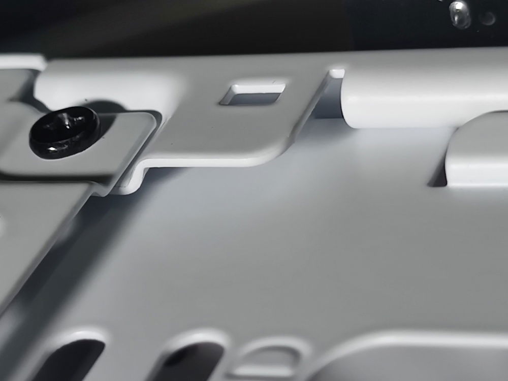
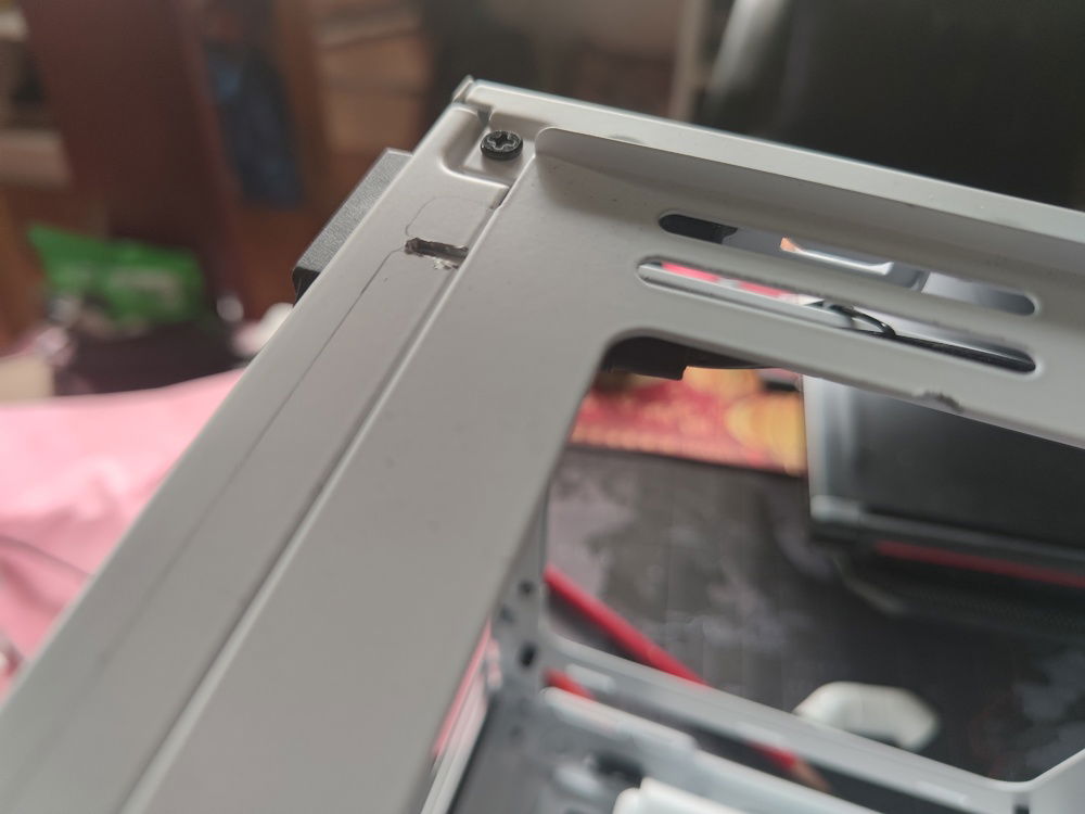
I had to grind off some of the mounting pins and also cut a channel where the raised metal of the bracket would fit.
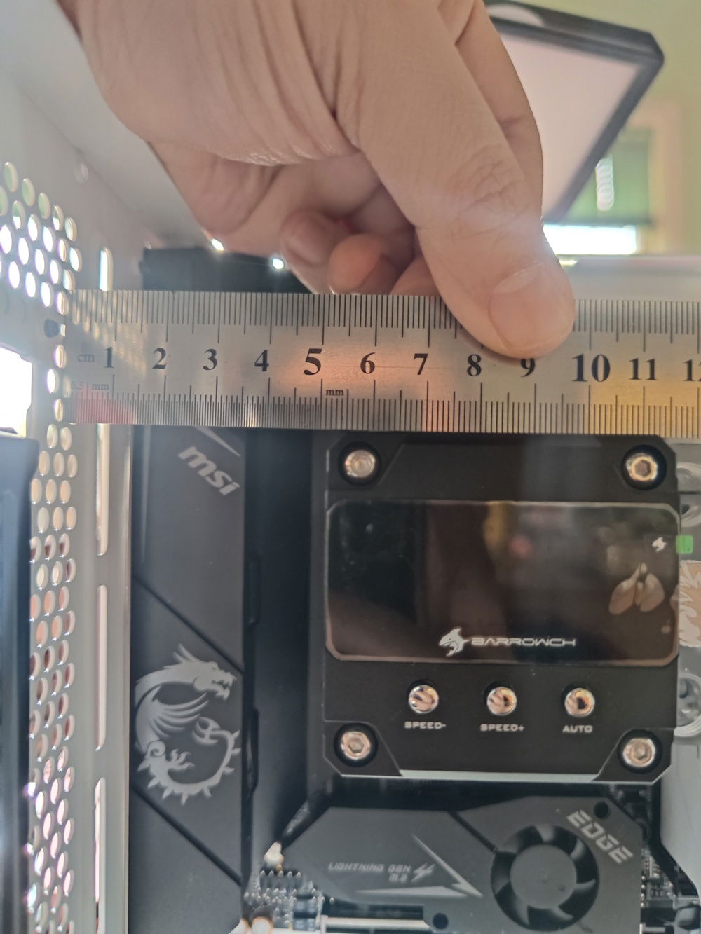
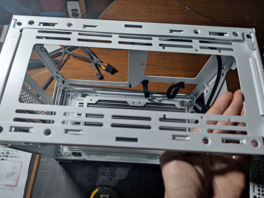
I also measured out the clearance I'd have for a 25mm thick, 92mm radiator plus fan combo, as well as the clearance for the tubing from the top radiator.
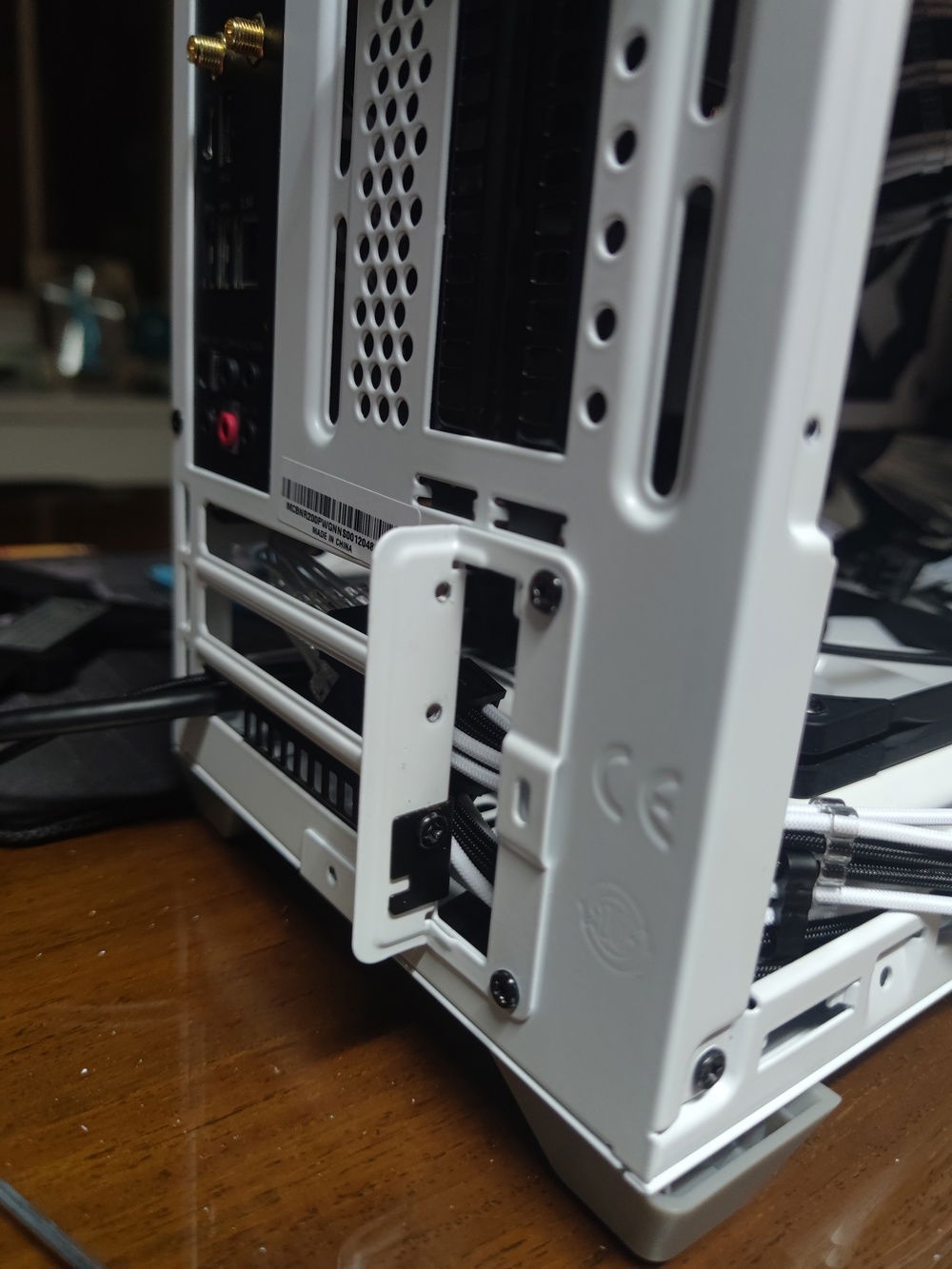
On the other hand, reversing the bracket, with the edges facing upwards, enabled me to save another 1-2 millimeters, with only minimal additionalmodding to the top plastic panel.
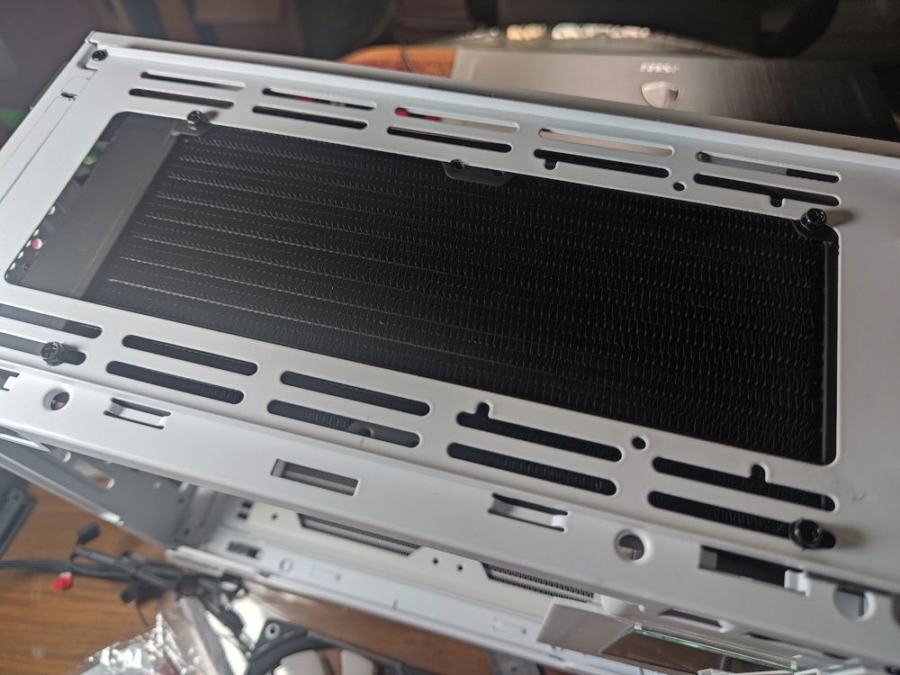
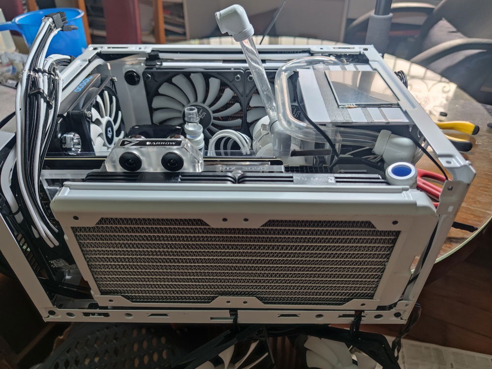
The radiator mounted. I moved it to the side towards the glass panel to clear the power cable housing on the other side.
This also created space on the other side where I could hide/route my cabling.
Without any components, it looked like I had a ton of clearance.
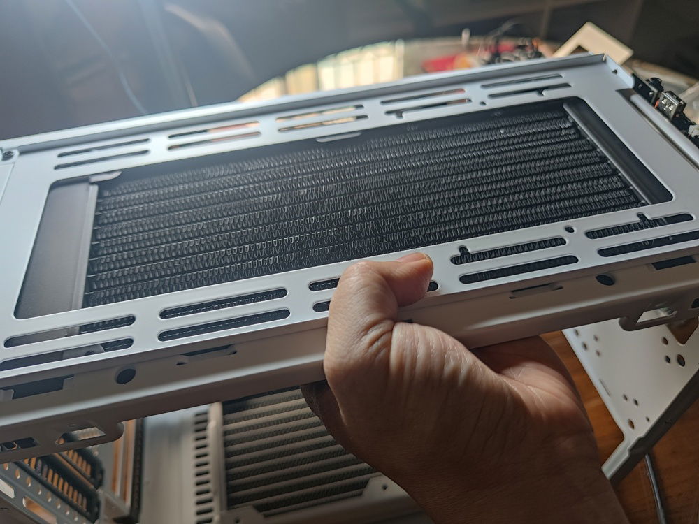
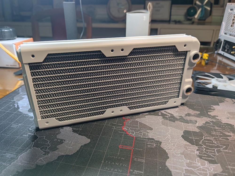
Painting the radiator satin white, to match my bottom HWL Nemesis satin white rad.
Tapping the screw holes made for a secure mount for the top radiator.
The Kaze Slim fans arrived.
I had to shave off some of the RAM heat spreader to avoid them catching on the fan blades. There goes my warranty.
This looks fine. But in fact, the fans had a little wobble built in so it looked like it had less than a millimeter of clearance while it was spinning.
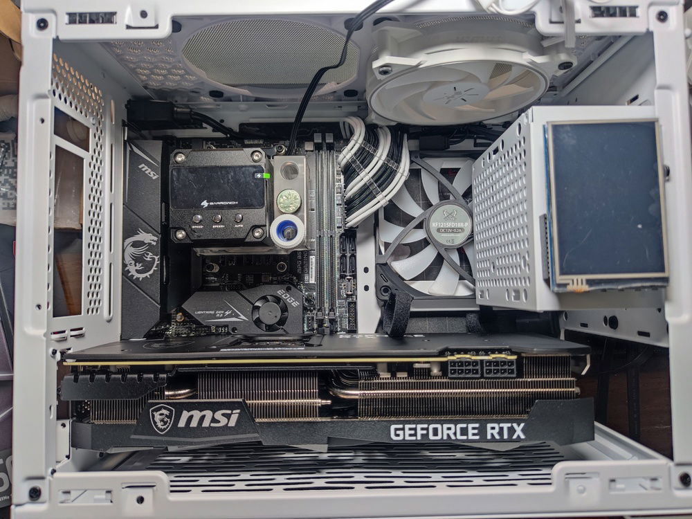
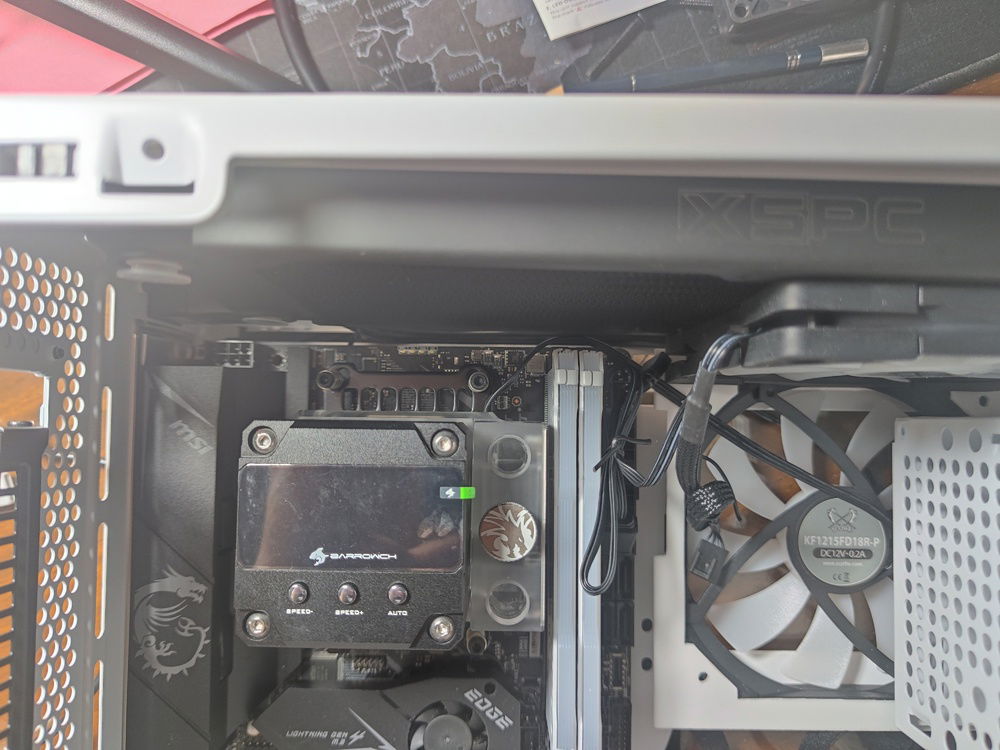
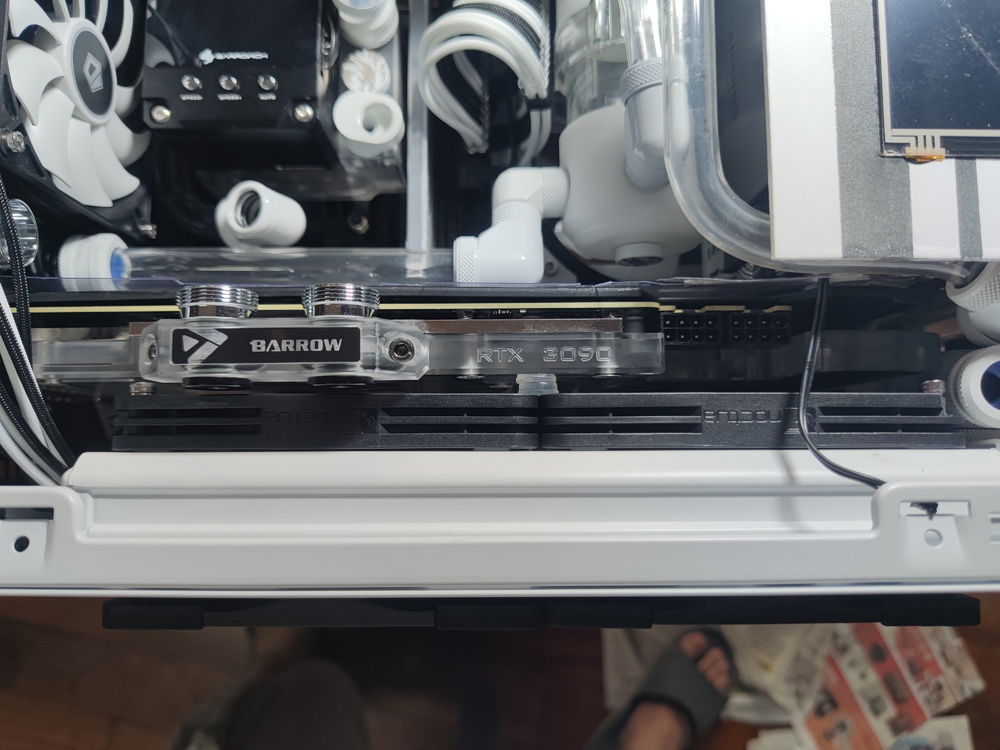
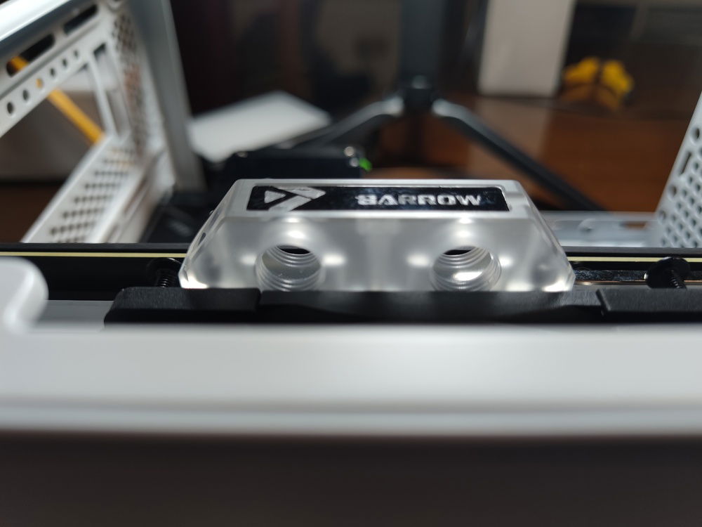
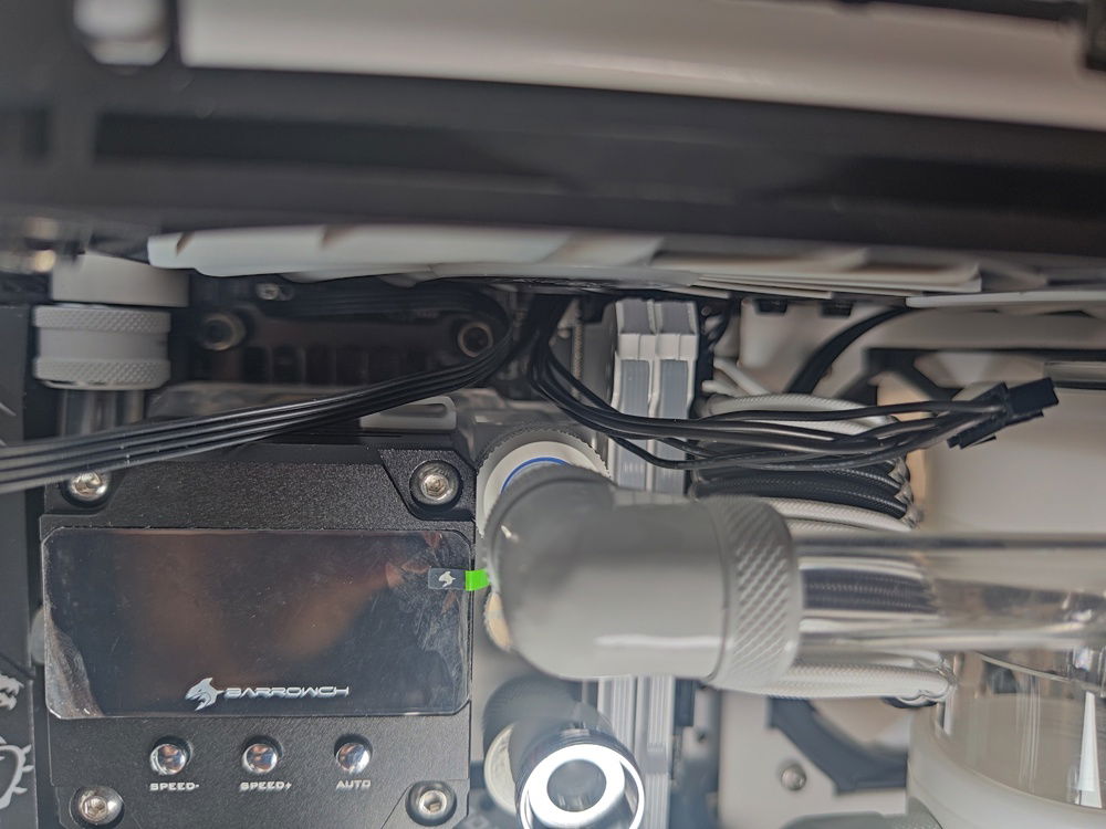
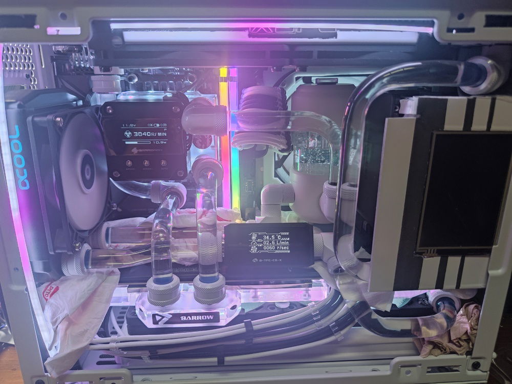
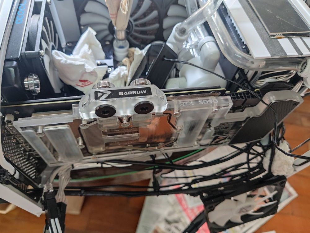
The Barrow combo pump / reservoir / block was perfect for this compact build.
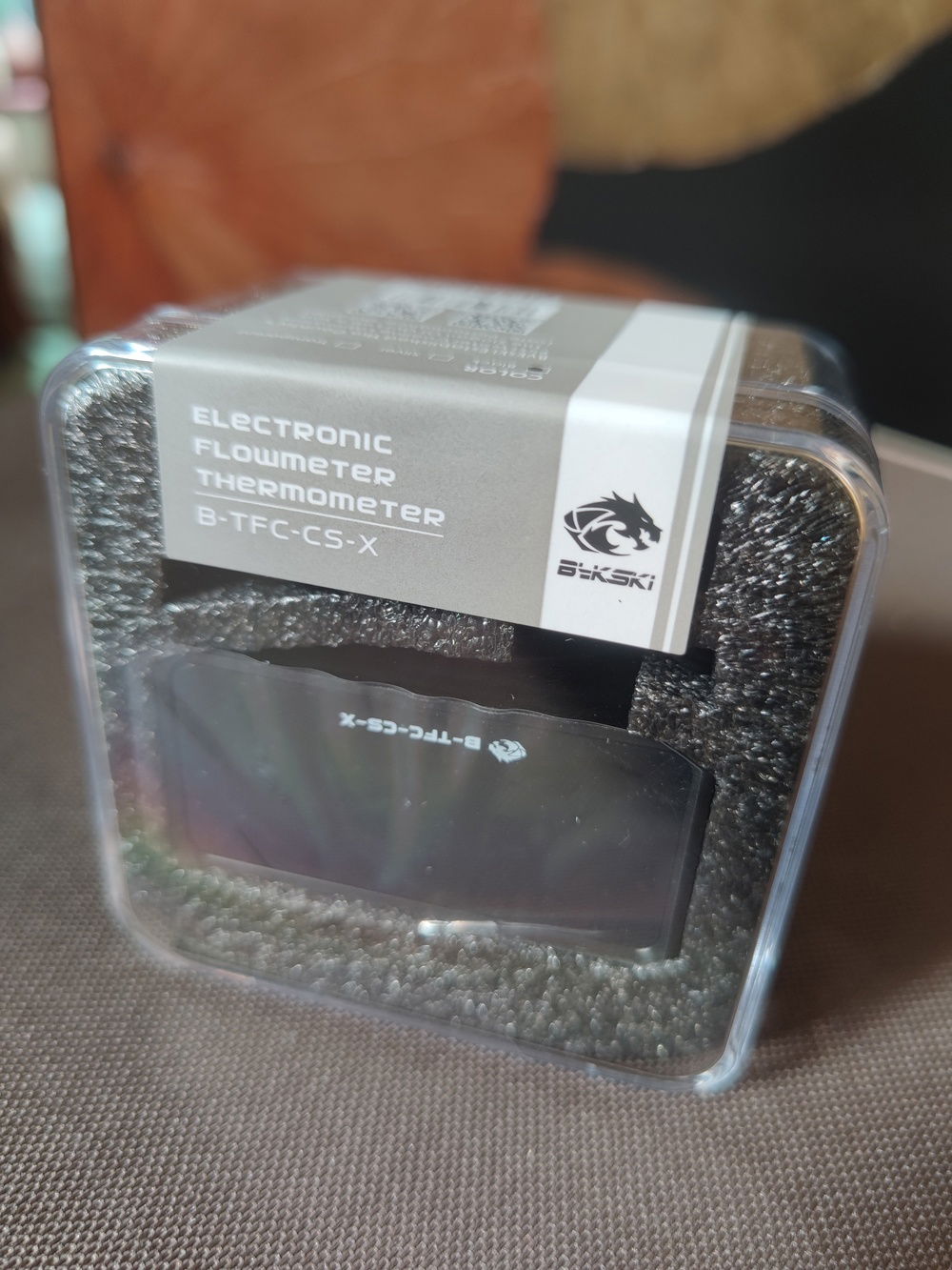
Bykski flowmeter / thermometer.
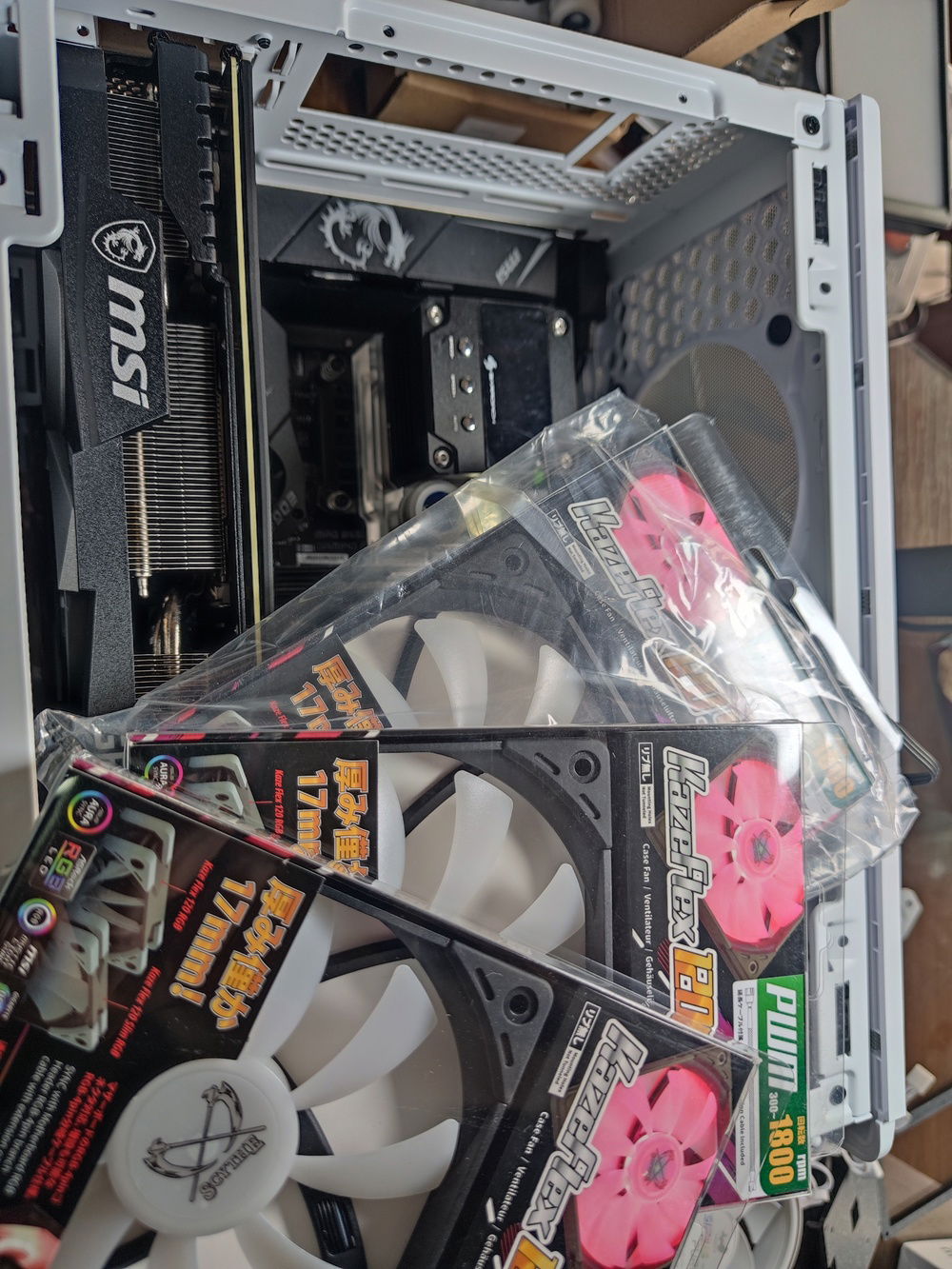
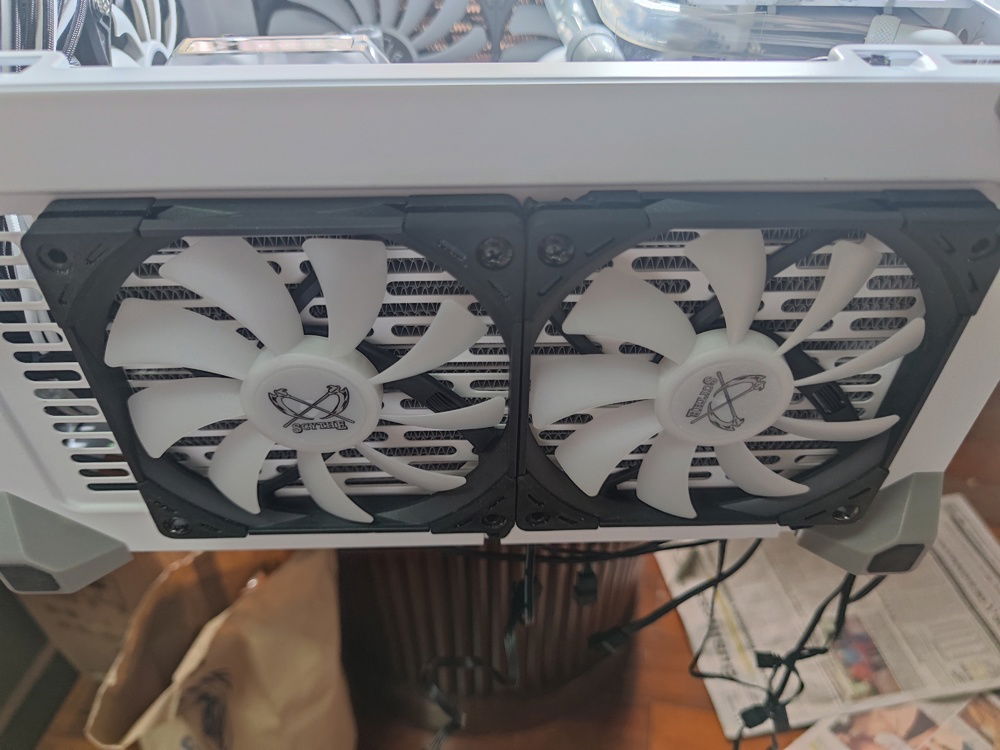
17mm fans proved to be too thick for my top mount rad, but was perfect as bottom, external push fans.
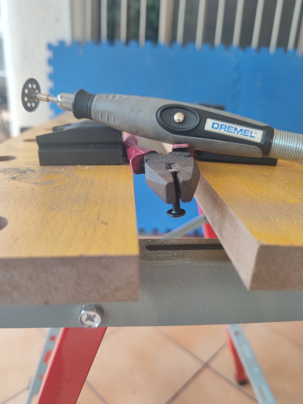
My hacked together screw-cutting setup.
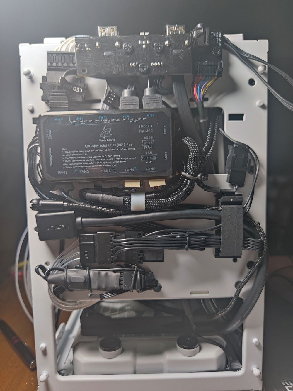
No space for mounting SSDs at the front. Side note, the HDMI and USB cables leading to the screen in at center-left, right below the fan/RGB hub.
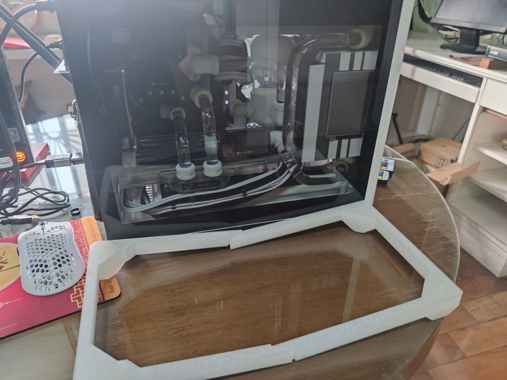
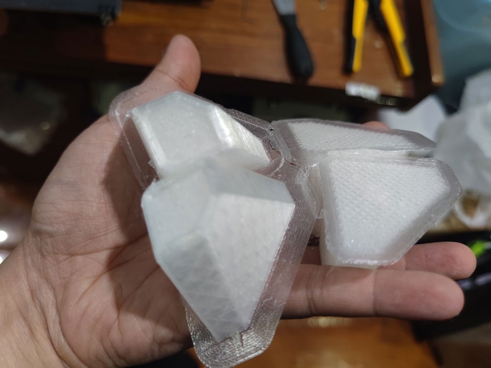
Here is the riser, still unassembled.
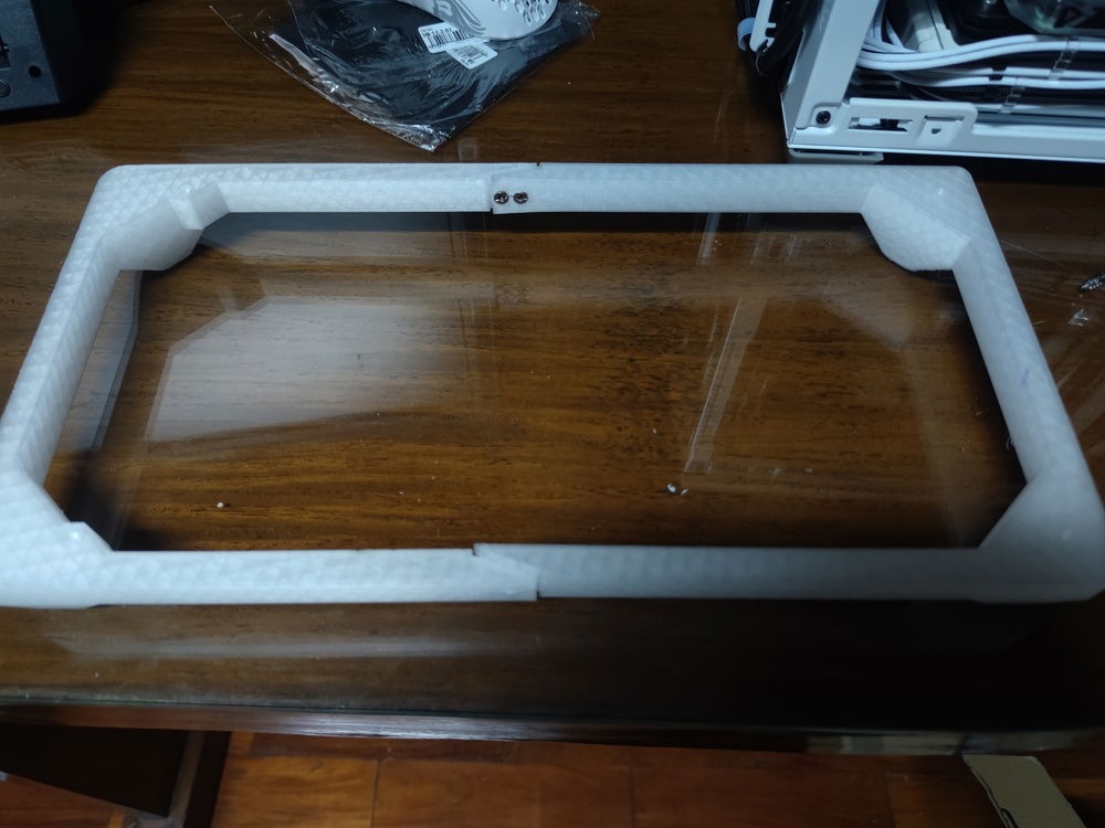
Two screws on each side joined the two pieces together.
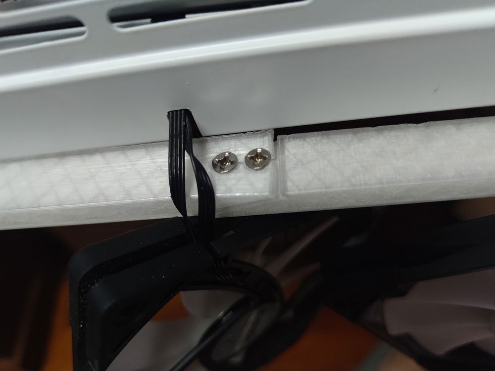
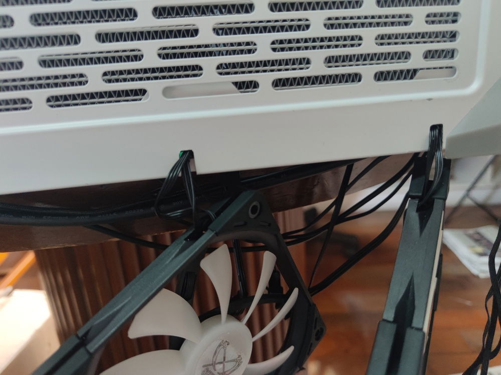
The riser hides the fans from view (unless you really peek under the case) as well as the cables leading into the case.
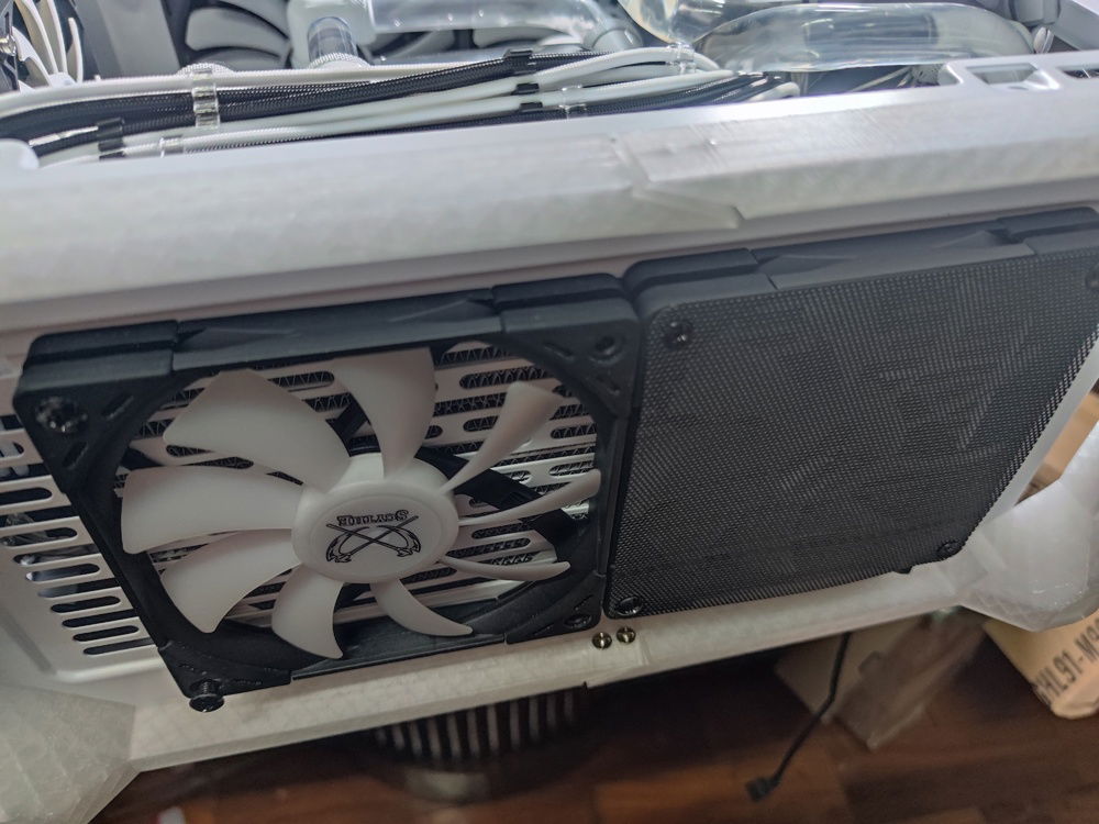
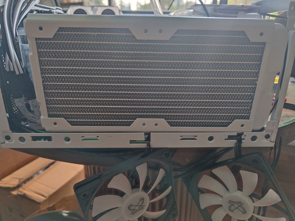
Fans secured onto the radiator inside and the case itself. Mesh filters also required.
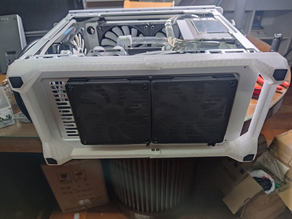
Finished. I intentionally chose RGB external fans to create a subtle underglow if I choose to turn on my RGB. The gap to the left of this picture is where the metal cover on the NR200 goes.
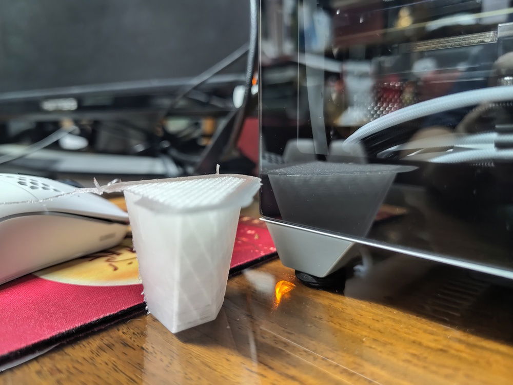
Here is a comparison of the default feet versus the installed riser. Enough space for ventilation and keeps the look of the whole case clean.
HDMI and USB cable pass through to the rear of the PC for connecting to the GPU
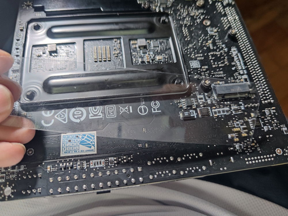
Plastic on motherboard rear for additional insulation for cables.
Most of the cables were hidden behind the PSU cage and out through to the front of the case and hidden behind the metal front decorative panel.
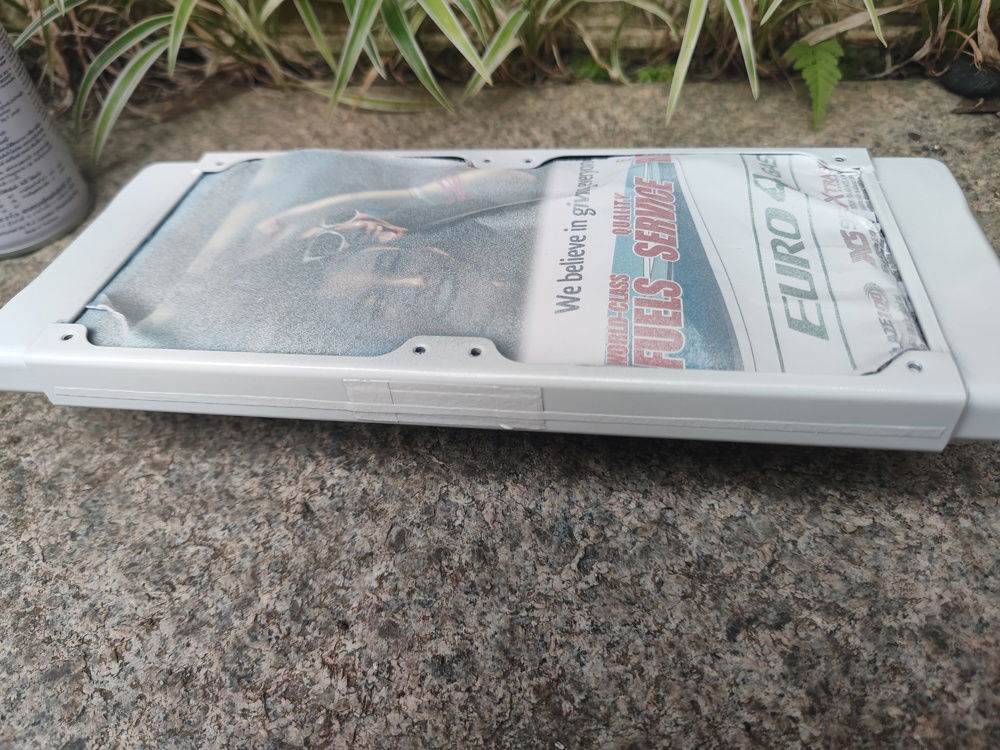
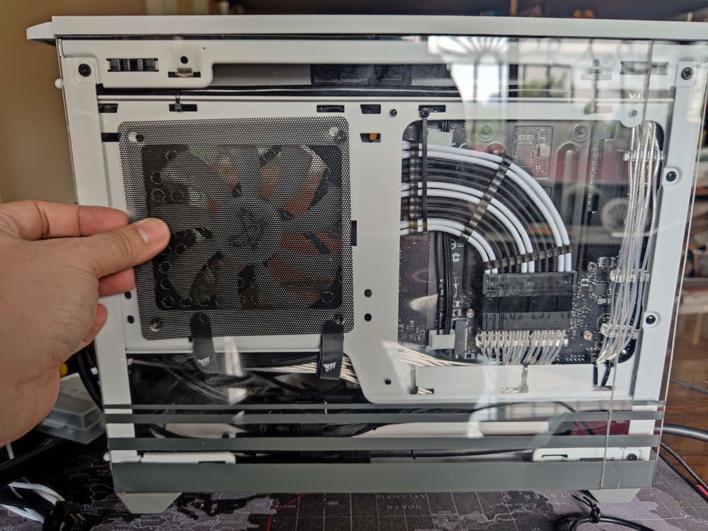
The rear panel was created to show off the sleeved cabling and cleaned rear portion of the case.
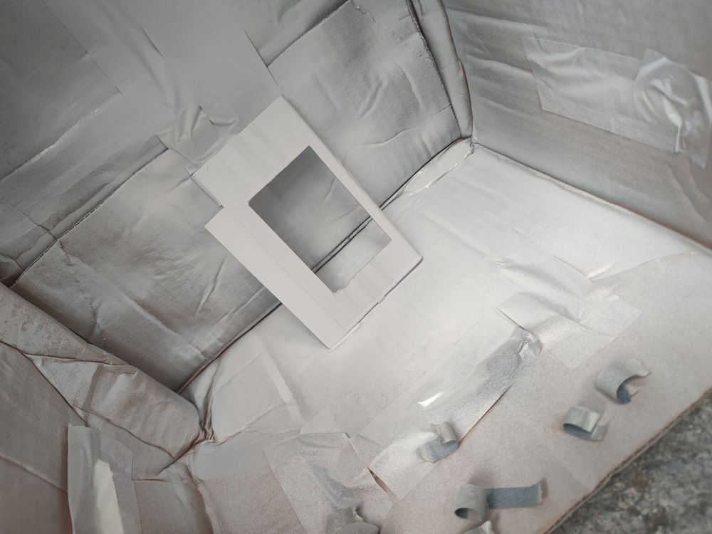
The additional acrylic pieces covered the horizontal VGA slot holder and the vertical. This was done mostly to keep foreign objects out, including creepy crawlies.
I cut and glued some tabs that lined up with the NR200's slots onto the acrylic panel to hold it up when installed.
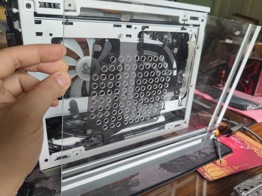
The side intake fan would need access to outside air, hence the ventilation holes.
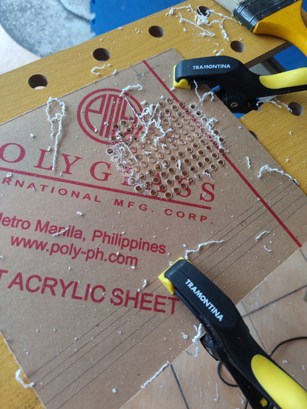
Acrylic cover cut and attached
I used a spare plastic mesh to filter the intake.
Note that the painted section was lined up with the black accents of the rear of the case. Gray and white was applied separately.
Creating the separate color lines took some time (and patience).
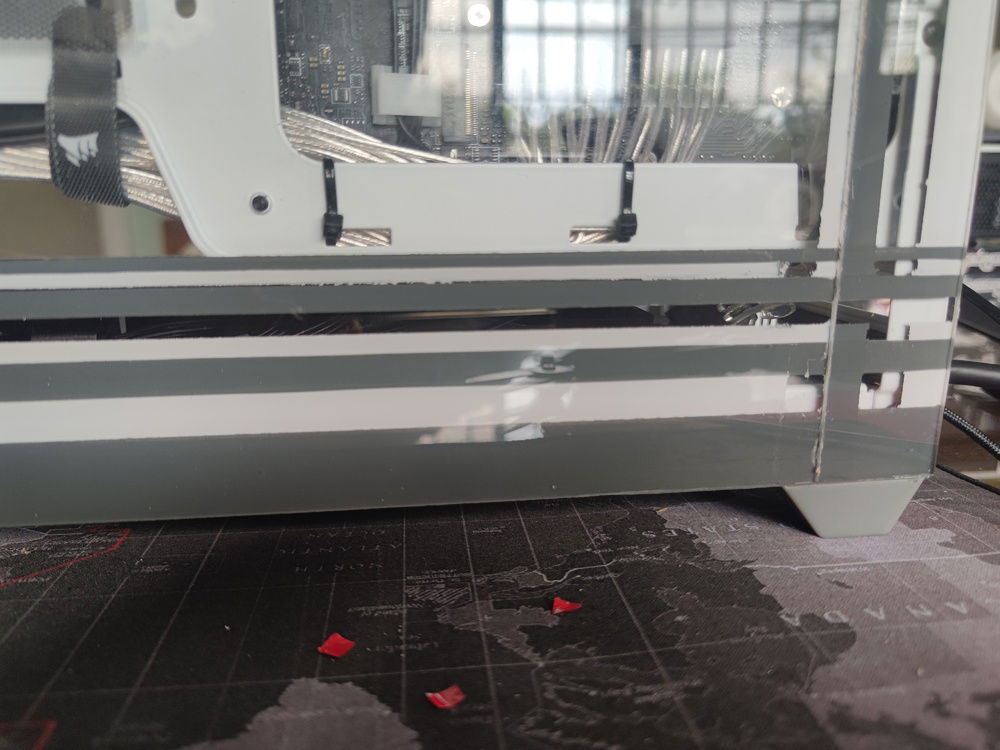
THe paint was far from acceptable at first. It took an additional three coats and three times masking off the separate lines to achieve the final result.
Rear panel and cable management done.
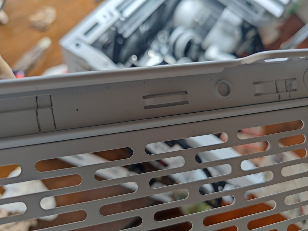
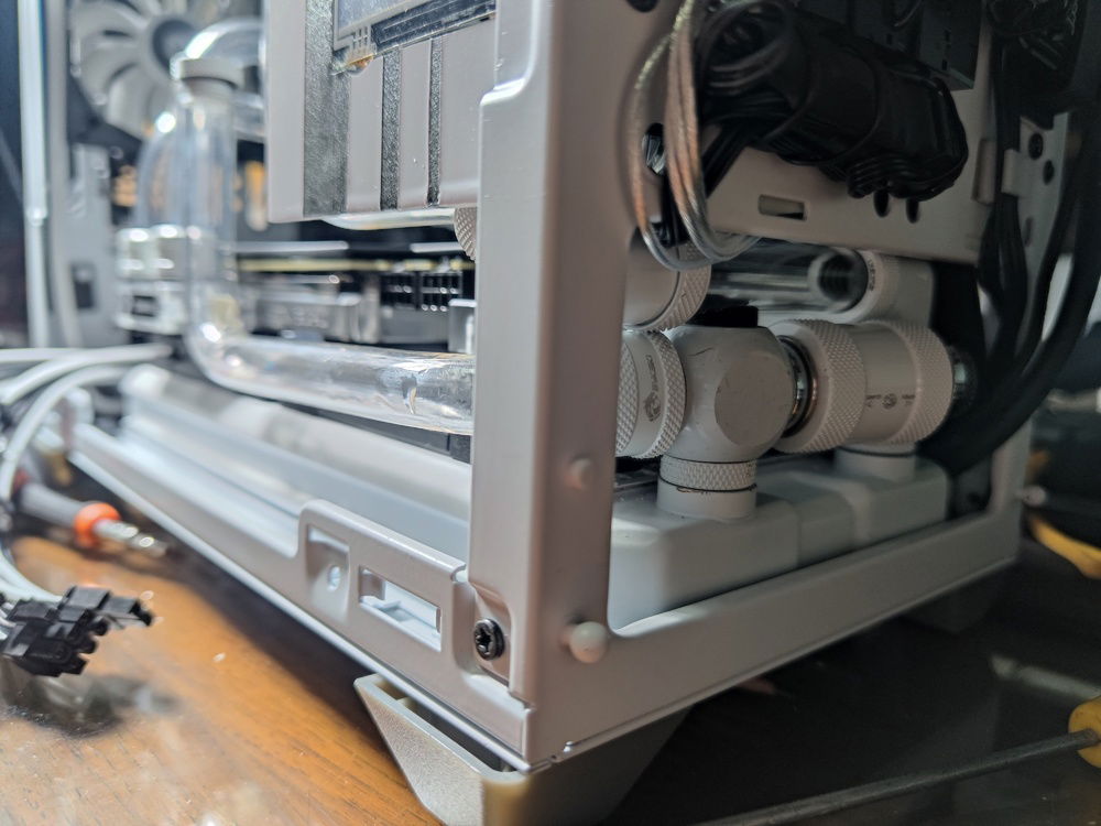
I wanted to find a way to minimize my cutting of the metal at the bottom to route cables for the external bottom push fans.
I decided on cutting channels into the interlocking bottom post and panel. This minimized cable runs for a clean look even underneath the PC.
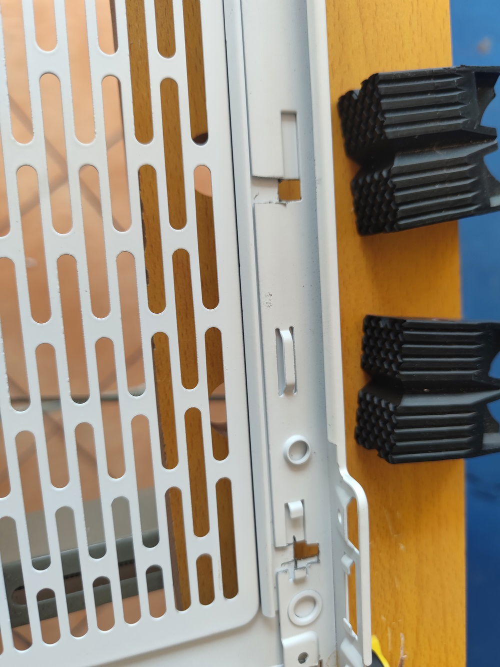
These are the interlocking post and bottom panel.
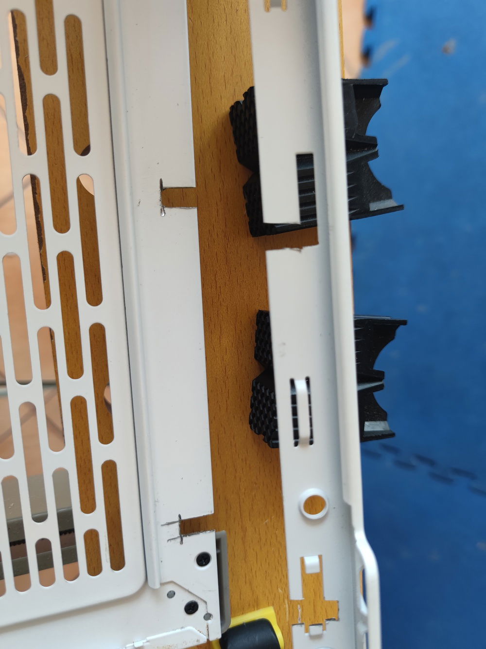
With the channels cut, combining the two would create a small hole just big enough for the cables.
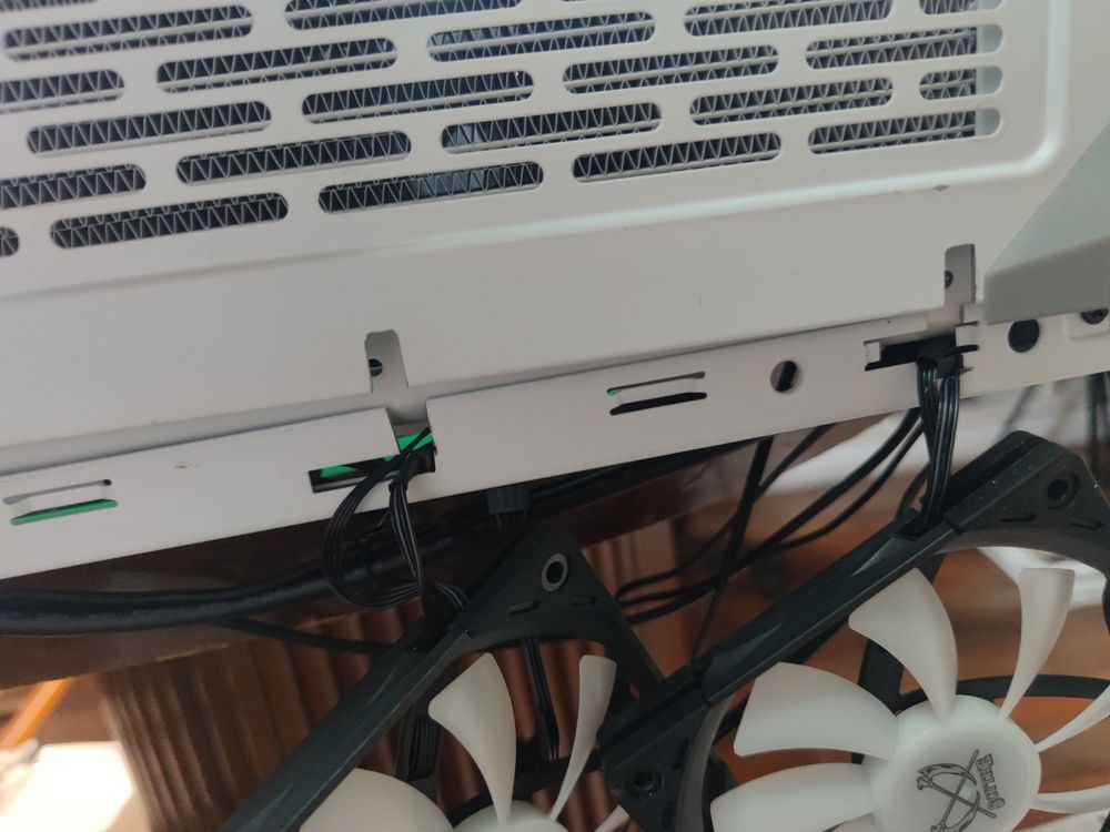
The wires leading to the external fans are less noticeable this way.
I experimented with three different feet for the NR200 - one was available from the Cooler Master website - which I rejected as it was not any higher than the standard, and this second version was certainly taller.
These feet lent an awkward look to the build, like the whole thing was on high heels. I started looking for an alternative.
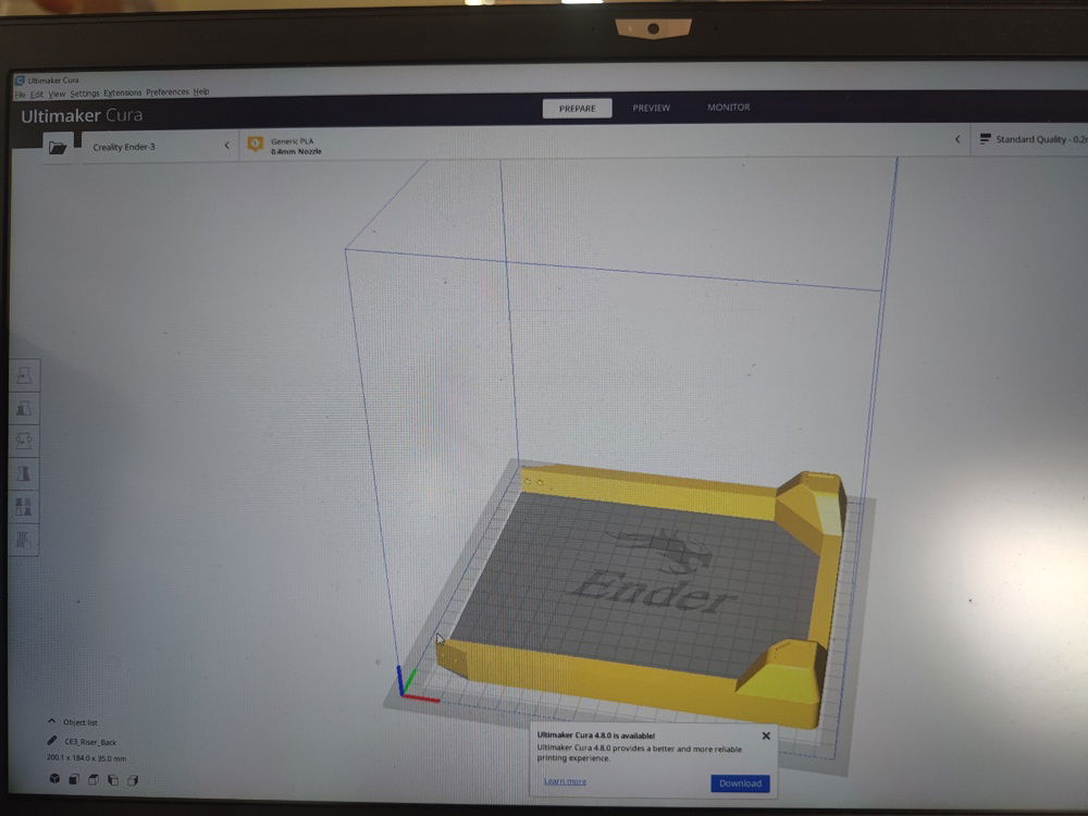
A generous soul shared his self-made stl files for a riser-style feet/shroud design for the the NR200, here seen in my slicer software.
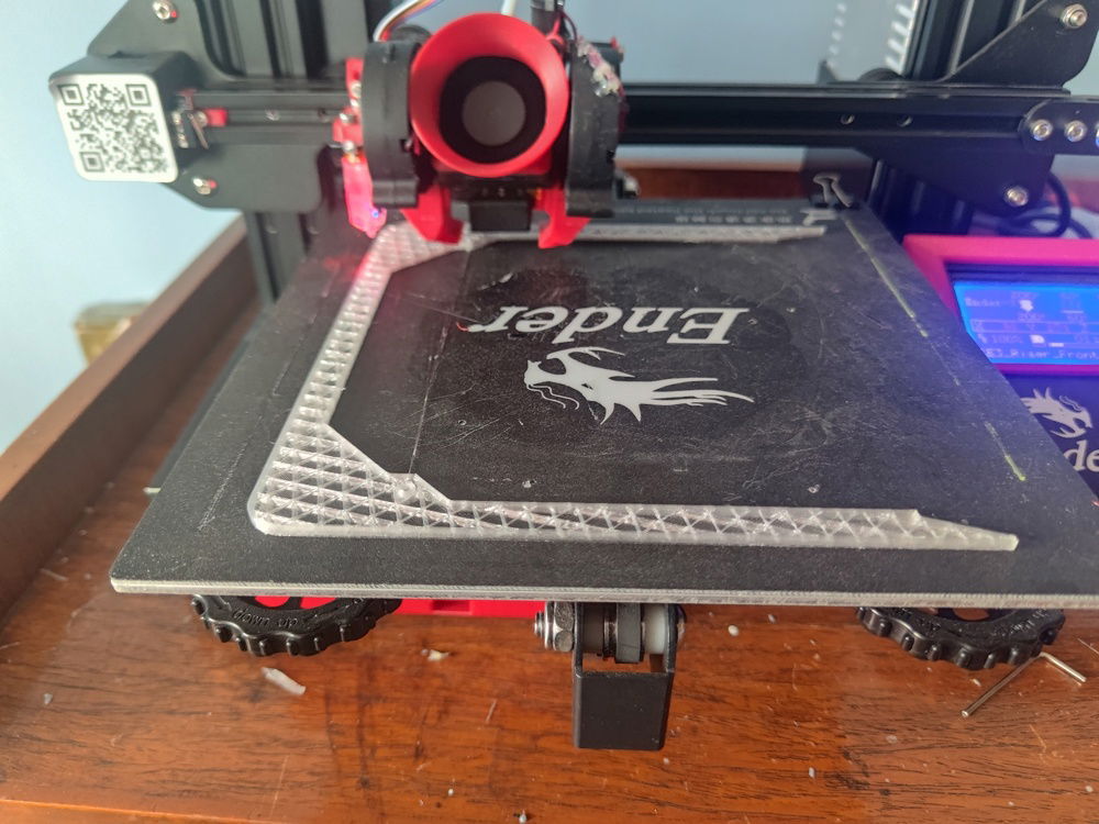
Started printing one-half of the feet.
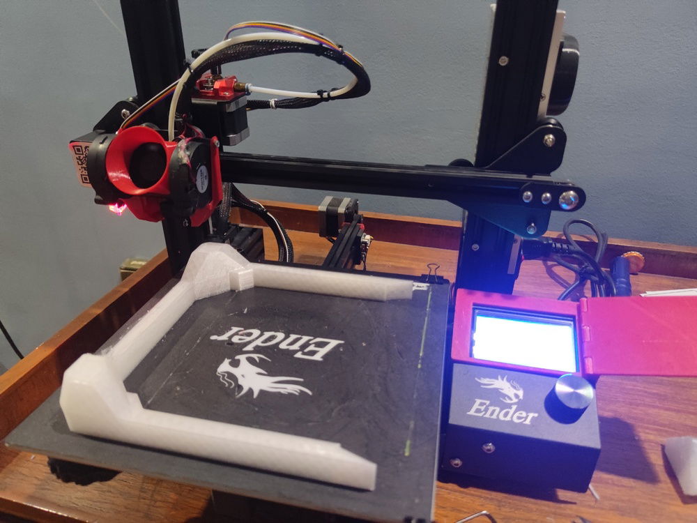
Done.
The new feet are slightly shorter than the stilettos, but gave more than enough clearance for good ventilation at the bottom of the case.

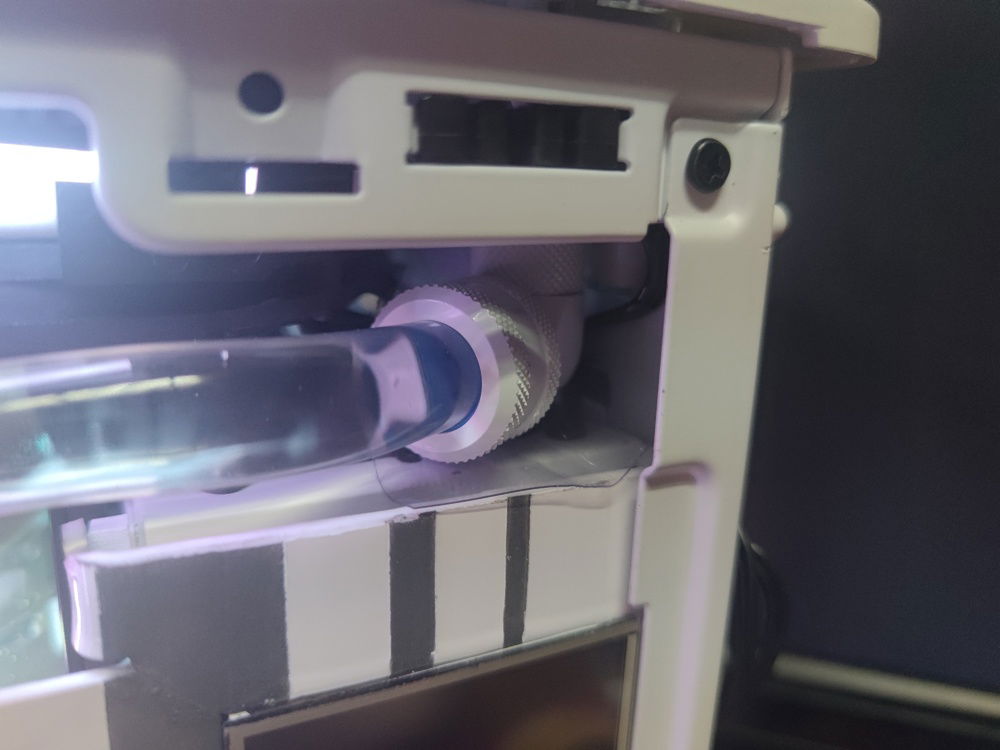
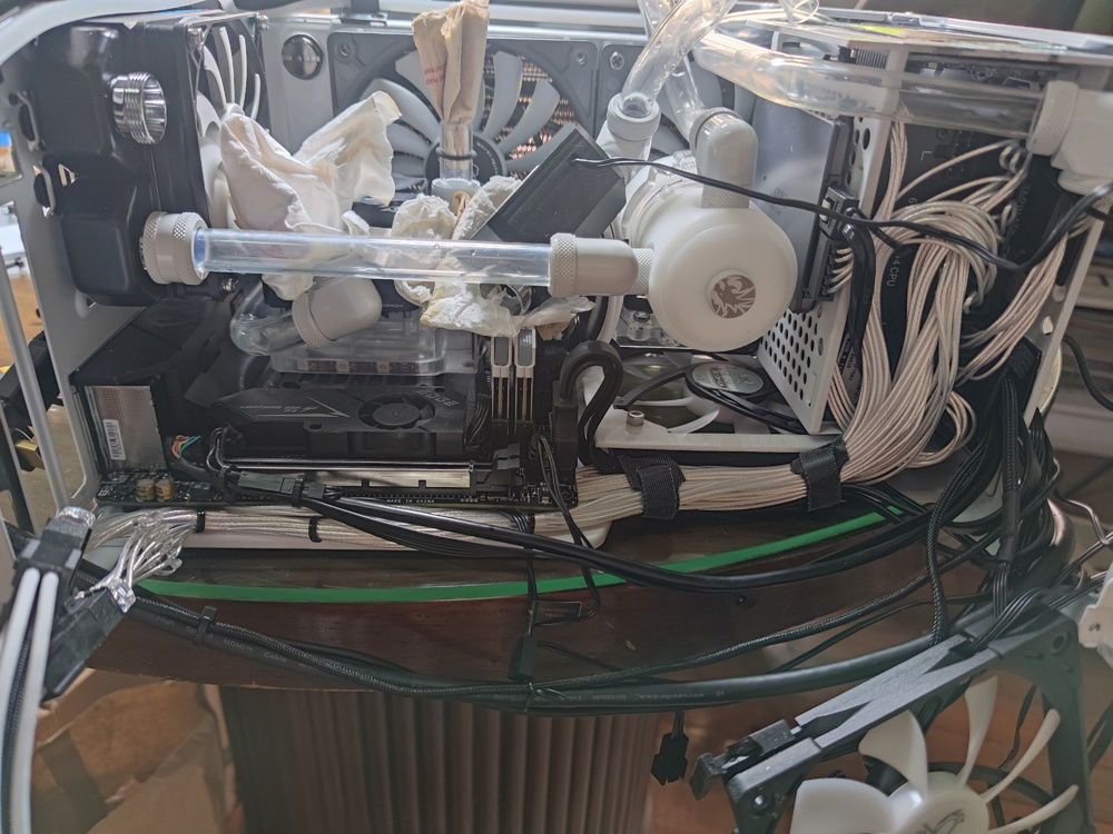
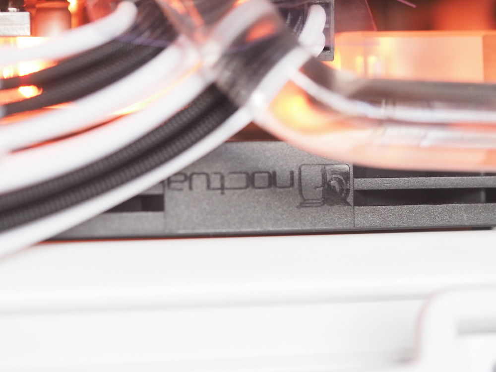
Some cutting required on the internal intake pull fans to clear the fitting. These fans were changed to Noctua slims in a future update (which were also mutilated and cut)

Same story with the upper fan - cut to clear the fitting. Also note the shroud / LCD frame on the PSU cage was cut down for the same reason.
The Noctua NF-A12x15 Chromax fans gave around 3mm of clearance from fan blades to the bottom of my GPU block.
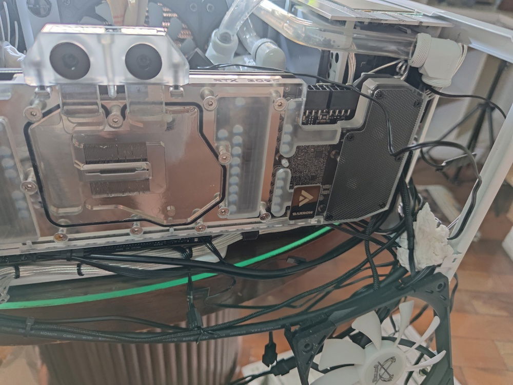
The Barrow GPU block did not extend far enough for me to able to use the bottom outlet/inlets.
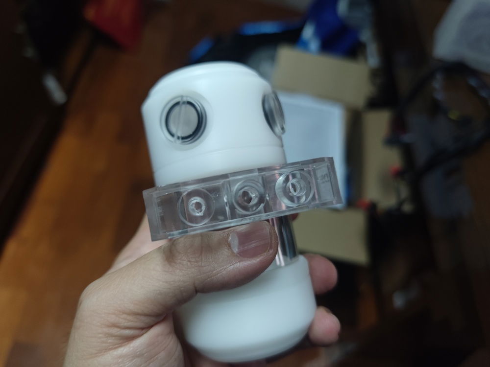
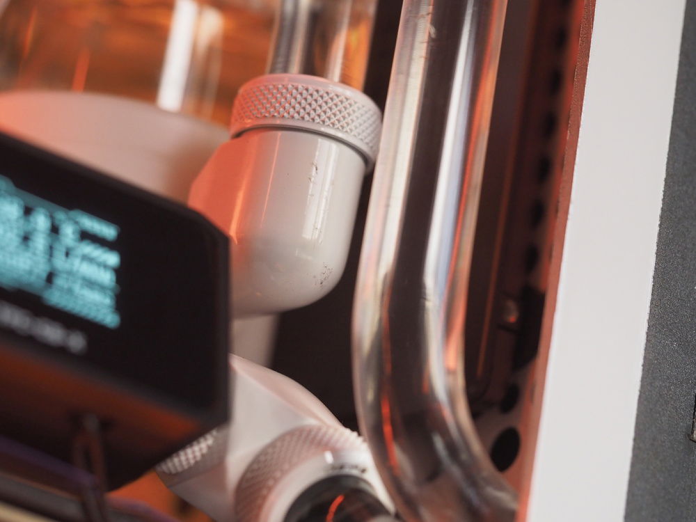
The reservoir choice was dictated by how much space was left between the GPU and the top radiator. The 100mm Reservoir from was perfect, if a tad tall for easy filling.
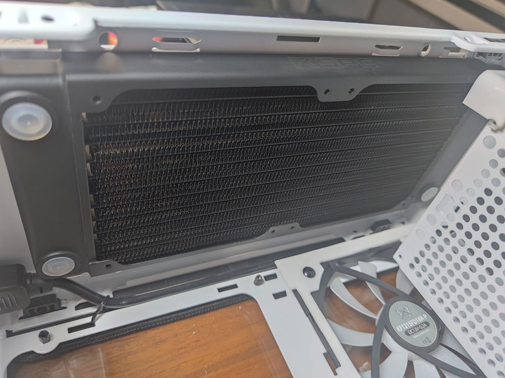
The top radiator choice was always the XSPC TX240, although I was tempted by the 17mm China-sourced radiator available on Alibaba or Taobao.
I went with the tried and true and almost regretted it when the fan blades on my 12mm thick fans still caught on my RAM sticks.
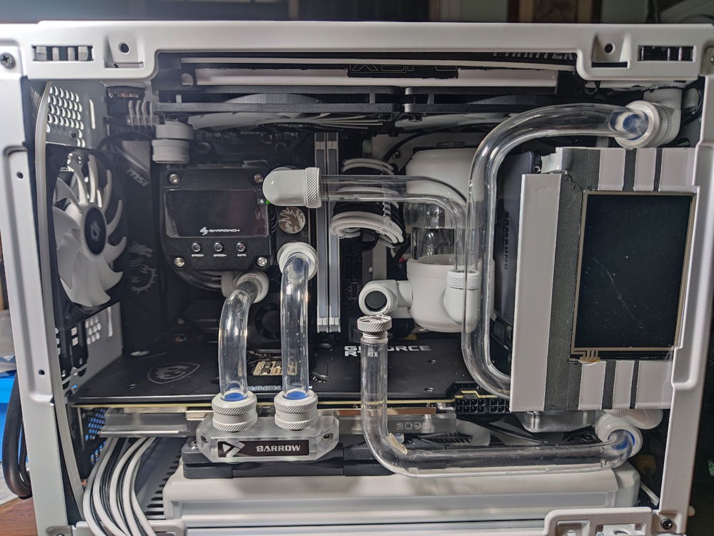
With space at a premium, most of the cables and paraphernalia ended up at the front of the case, hidden from view by the decorative metal front panel.
The whole build revolved around gaining enough clearance to fit all of the components and to some extent, ease access for future maintenance.
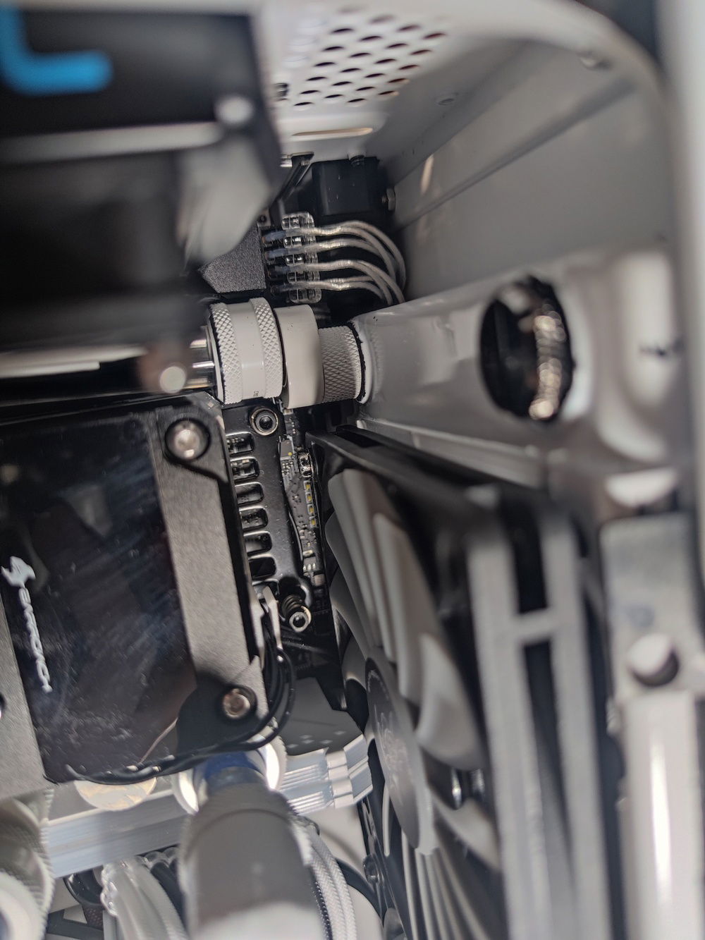
In this pic can be seen the cut made into the frame of the fan to clear the fitting and tube.
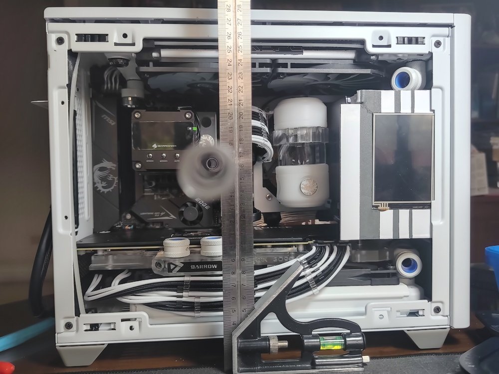
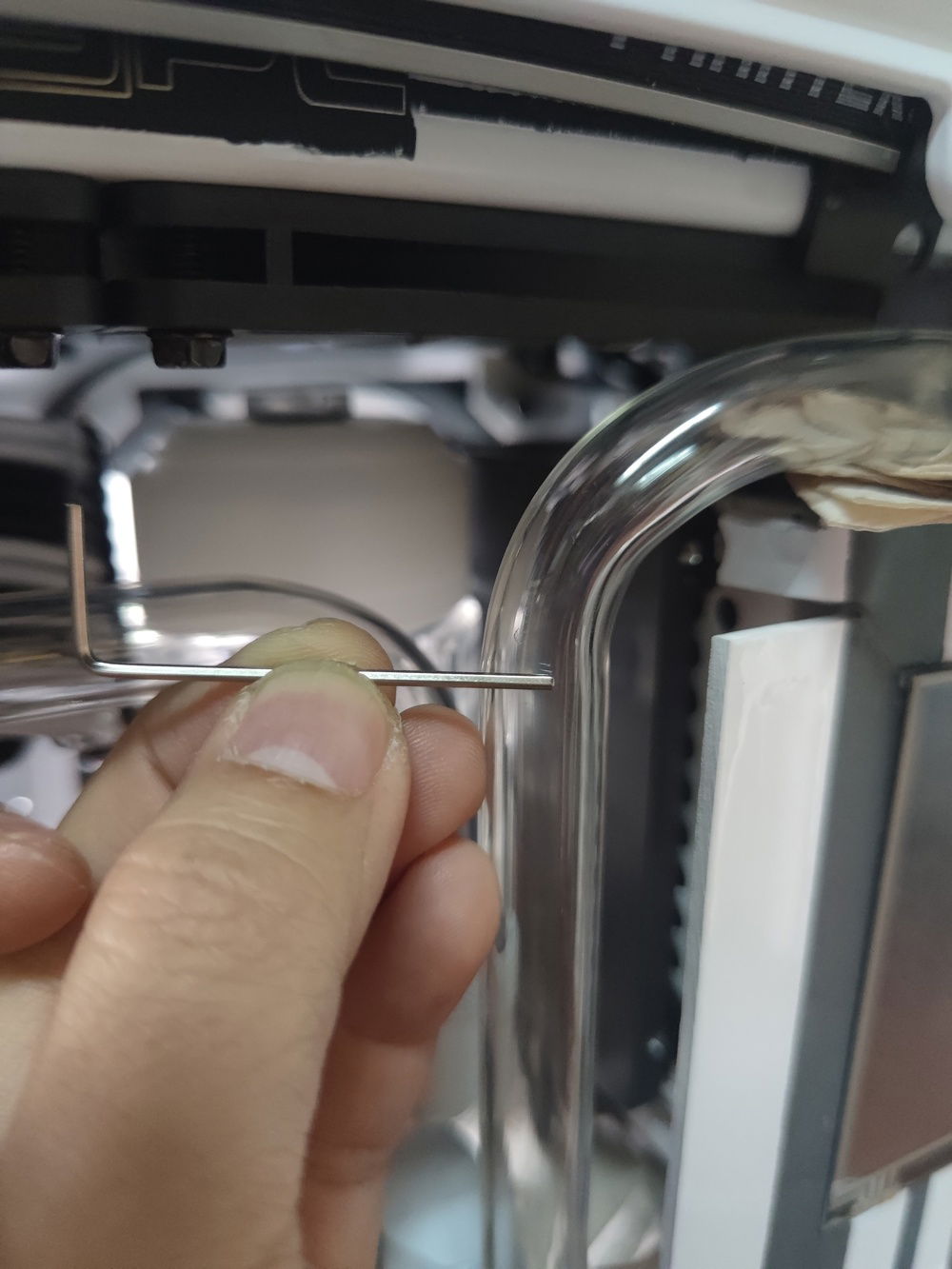
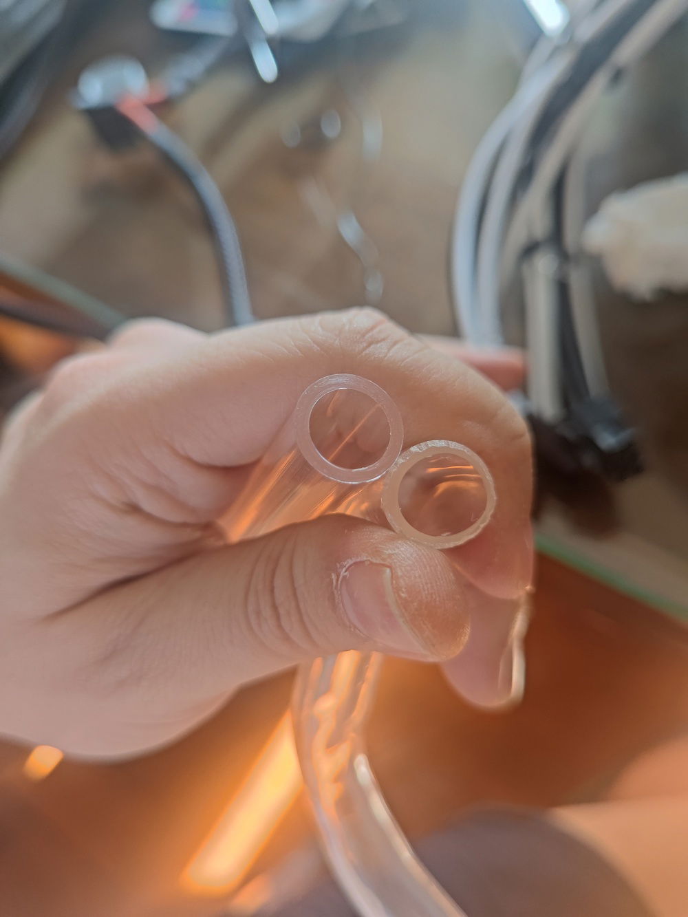
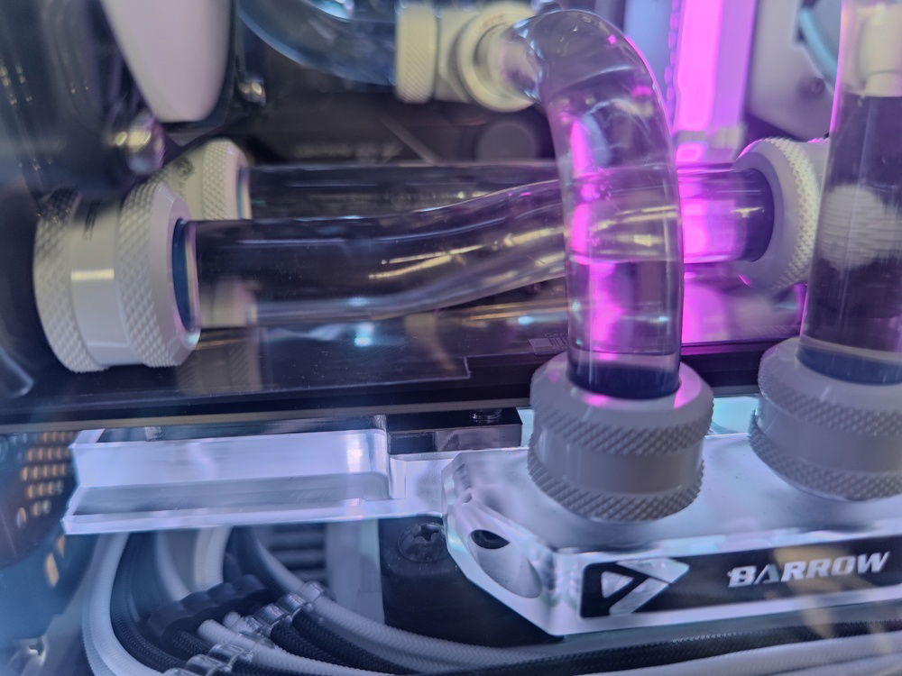
I bent my tubes by using longer than required tubes and connecting to the fittings when possible so I could envision where I needed the bends and where the fittings and tubes would meet up.
In this case I determined that I would not be able to use fittings for the bends due to the proximity of the tempered glass panel. But also for aesthetic's sake.
Another view. I also had to clear the power cable at lower middle of the pic.
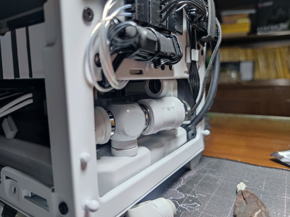
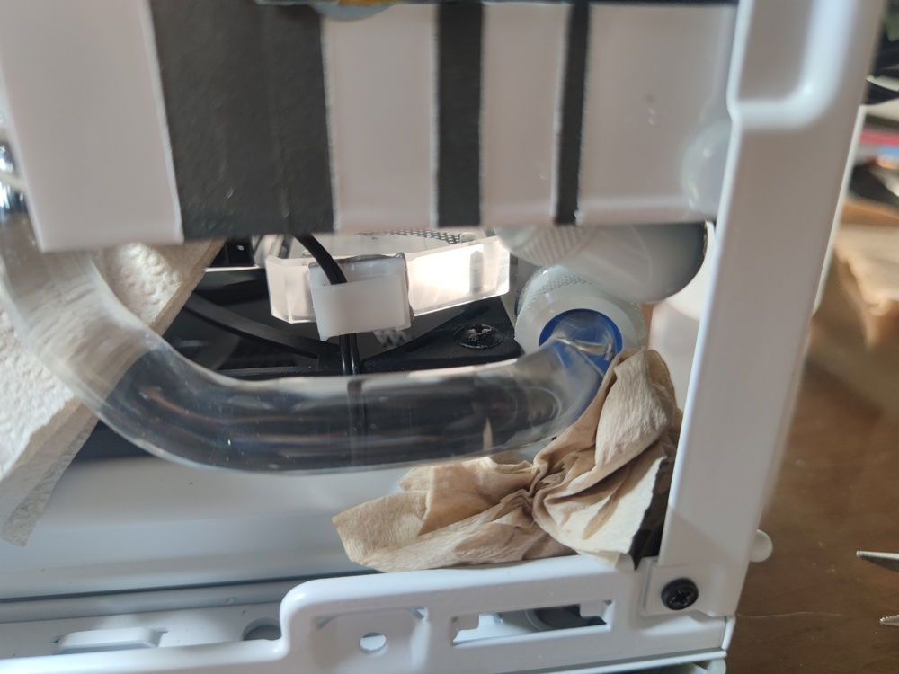
A closer view of the drain system. It was super tight in this area due to my mistaken assumption that my tubes would fit under the PSU cage (it woyld not due to the PSU cables - even after cable management.)
The bottom radiator clearance is more of the same. Some fan frame material had to be cut away (same with the Noctuas that replaced the fans in this pic) to clear the fitting and tubing.

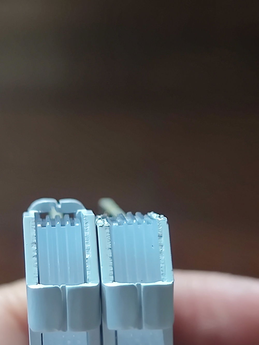
I went with compressible PSU cables to create enough space below the PSU. The original plan was to route the tubing below the PSU cage, but there was no way to do that, as the fittings alone would not fit.
A pause after all of the setup and planning. At this point I had a general idea of where my tube runs would go, but knew enough to expect that things would change because of clearance, bending, or fitting issues.
I was also waiting for one final component (the 92mm radiator) at this point.
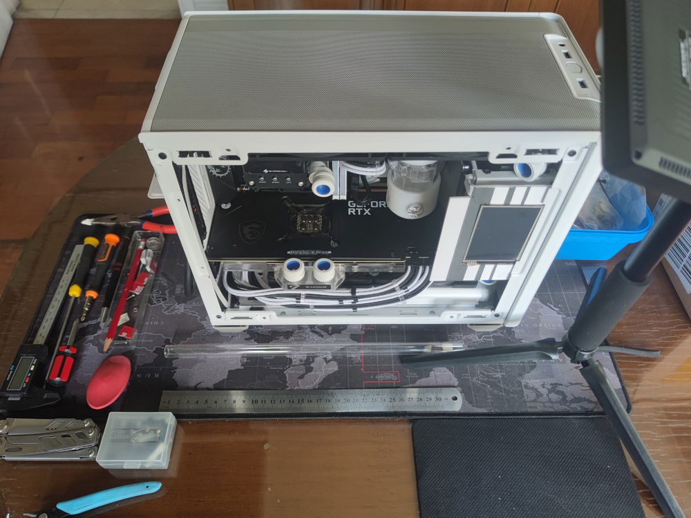
Arranging my tools before the bedlam.
I started with the easier bends - in this case the 90 degree bend from the pump to the GPU block.
The GPU to top rad tube was almost as easy - I just had to twist the compression fitting on the top radiator with a long nose; making sure not to over-tighten.
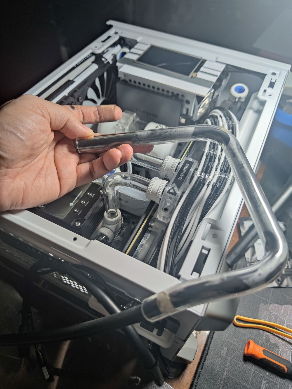
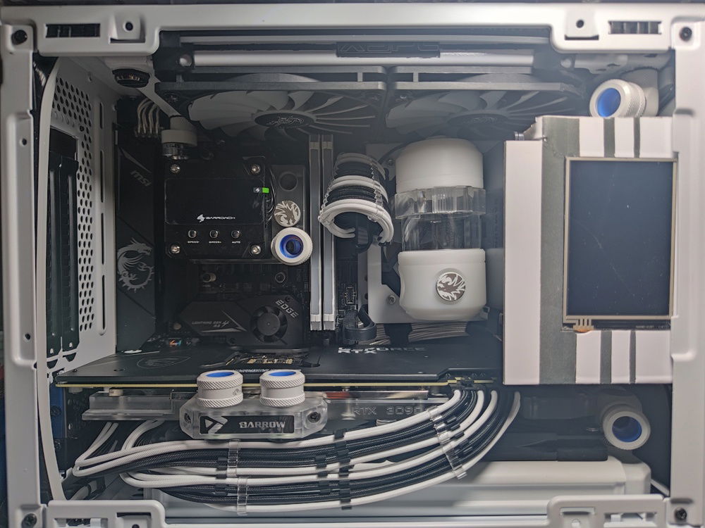
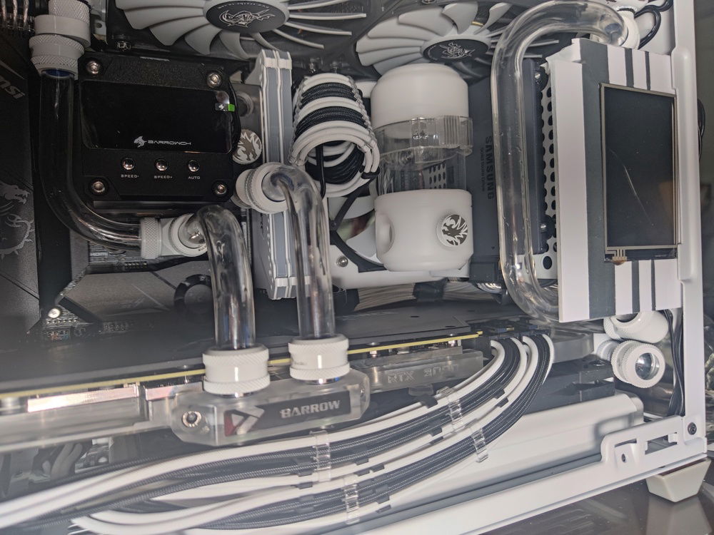
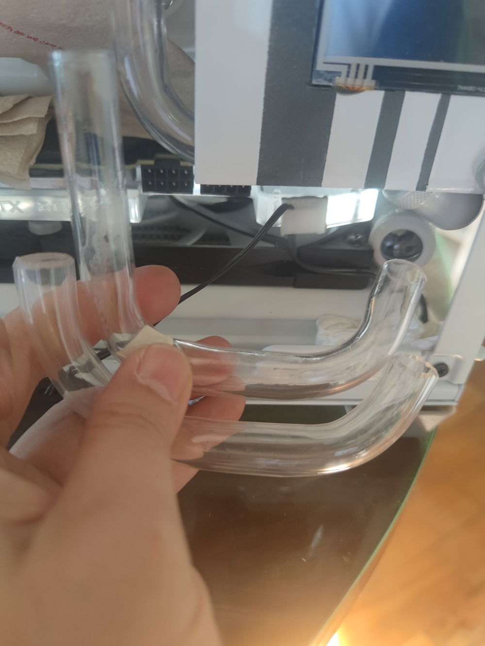
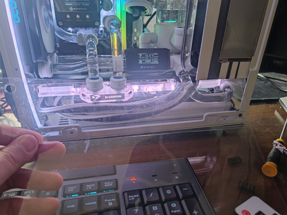
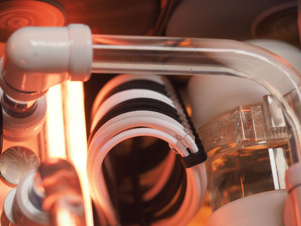
This tube connects the top radiator to the bottom one, bypassing the PSU cage due to necessity. It consists of two complex bends top and bottom to clear the side panel.
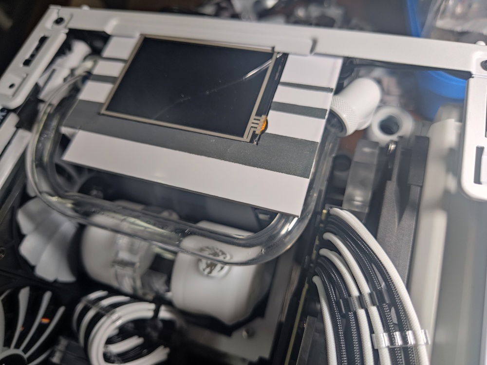
It turned into a kind of centerpiece and frame for the internal LCD, I'm happy how it turned out.
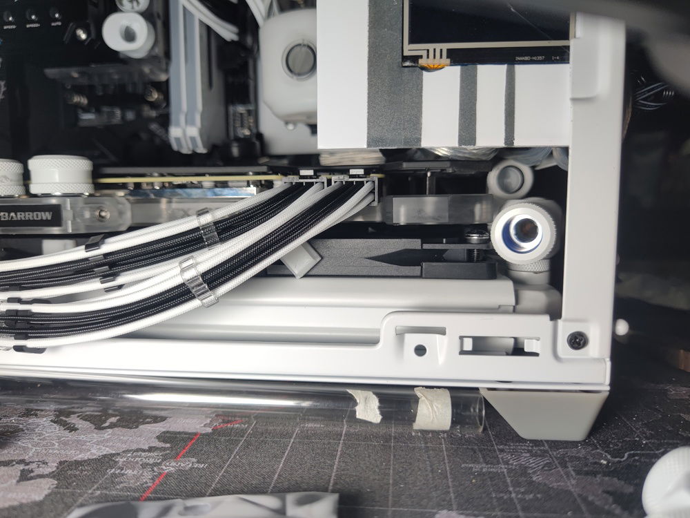
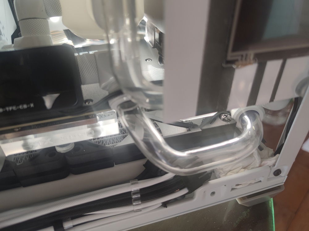
The top to bottom rad tube also had to clear the outlet tube which would have to clear the VGA power cables and reach up to above the GPU to run towards the rear of the case.
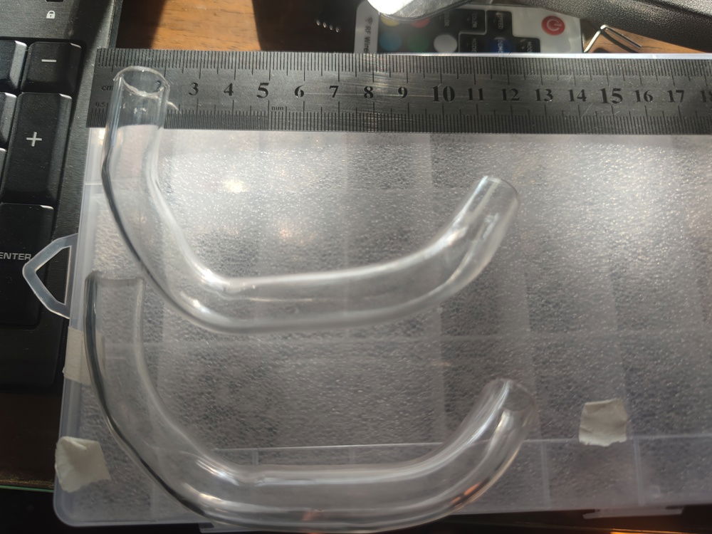
A successful bend, and it only took 3 tries.
The route of the outlet tube towards the rear can be seen from this angle. I wanted to line up the tubes to minimize clutter and keep the tube runs (looking) simple. This set of tubes was also supposed to line up with the tube coming out of the reservoir.
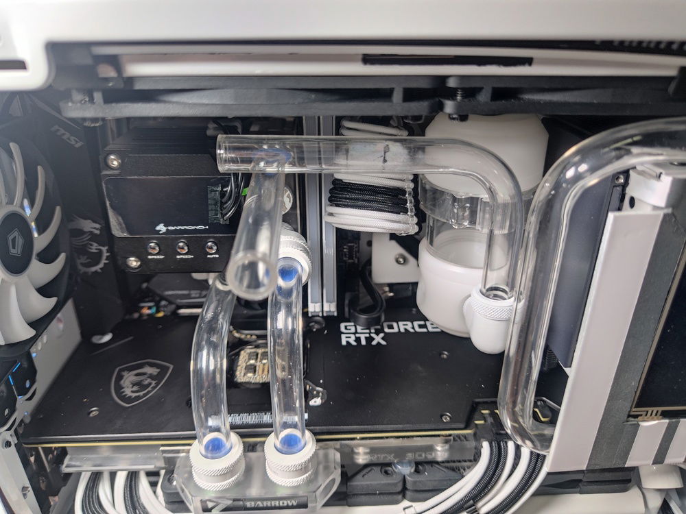
This pic best shows how I complete my tube runs. When possible, I extend my tubes to more easily visualize where my bends and/or fittings would meet and fit.
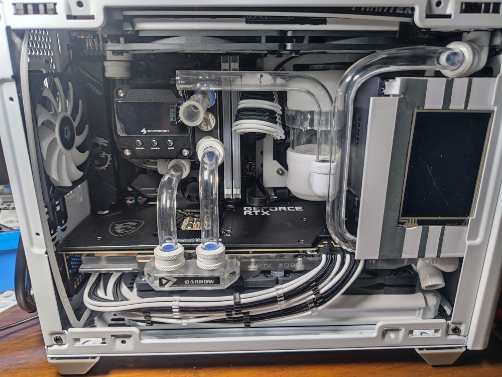
My first attempt at creating an even more complex bend from the bottom radiator to up over the VGA card.
When my rear radiator was delayed in the mail, I was seriously considering just completing the loop without waiting for it. This is the turning point of my build where I was deciding whether to just connect the two tubes you see crossing each other and just rebuilding when that last part arrived.
Another view of the bottom rad tube. I had to prevent it from touching the glass panel but I was constrained by the VGA power cables.
This view also shows why a fitting here would not work; there was just not enough space for fittings.
Even with 12mm thick Scythe Flex fans, I had to cut off some heat spreader material to prevent the blades from catching on the RAM sticks.
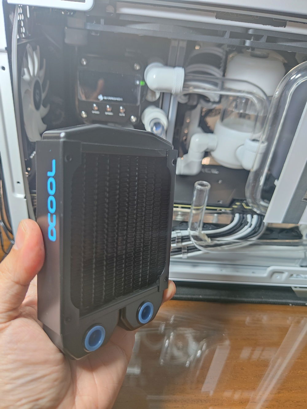
The rear 92mm radiator was less of a worry space wise - I wanted to fit the 45mm thick Alphacool 92mm radiator, but the tall Barrow CPU block/pump combo precluded that.
The most essential and unglamorous part of the testing process. It has been suggested to me to use a pressurizing leak tester, but I wanted to know where the leak was, if it leaked.
The components were protected reasonably well, and anyway, I only powered up the pump during testing
This is a view of the jumped PSU cable I used to test for leaks.
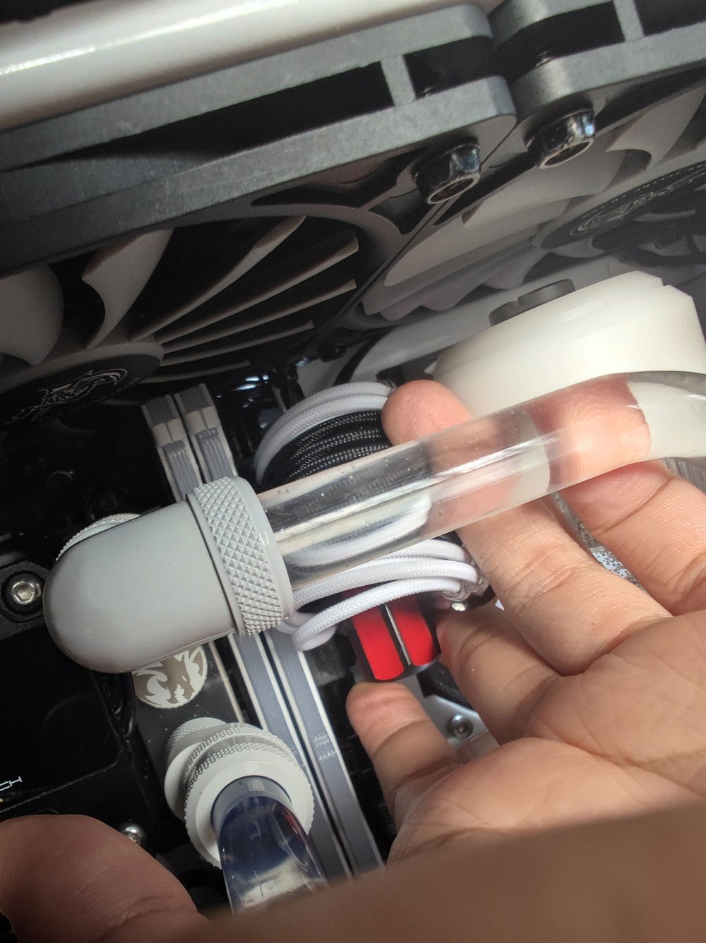
This is my reservoir opening tool (haha).
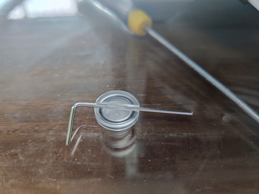
And that is the plug from the top of my reservoir.
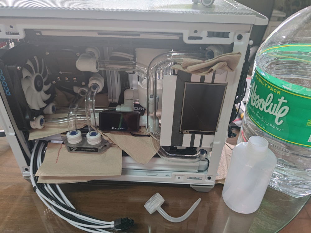
With so little space between the reservoir and the top radiator fans, I could not use my fingers to twist it open. I used the small hex tool for leverage and then a flexible tubed squeeze bottle to add water.
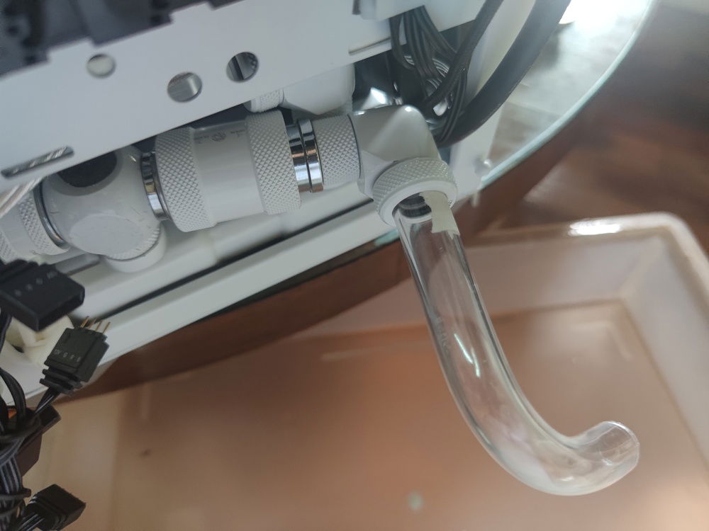
This is how draining the system would look. Barrow's push valve is easy to use but a bit loose. During normal operation, I double seal the valve using a plug.
Coming back to the leak, I discovered I had over heated the tube to the point that water was getting past the compression fitting rubber because it was no longer round.
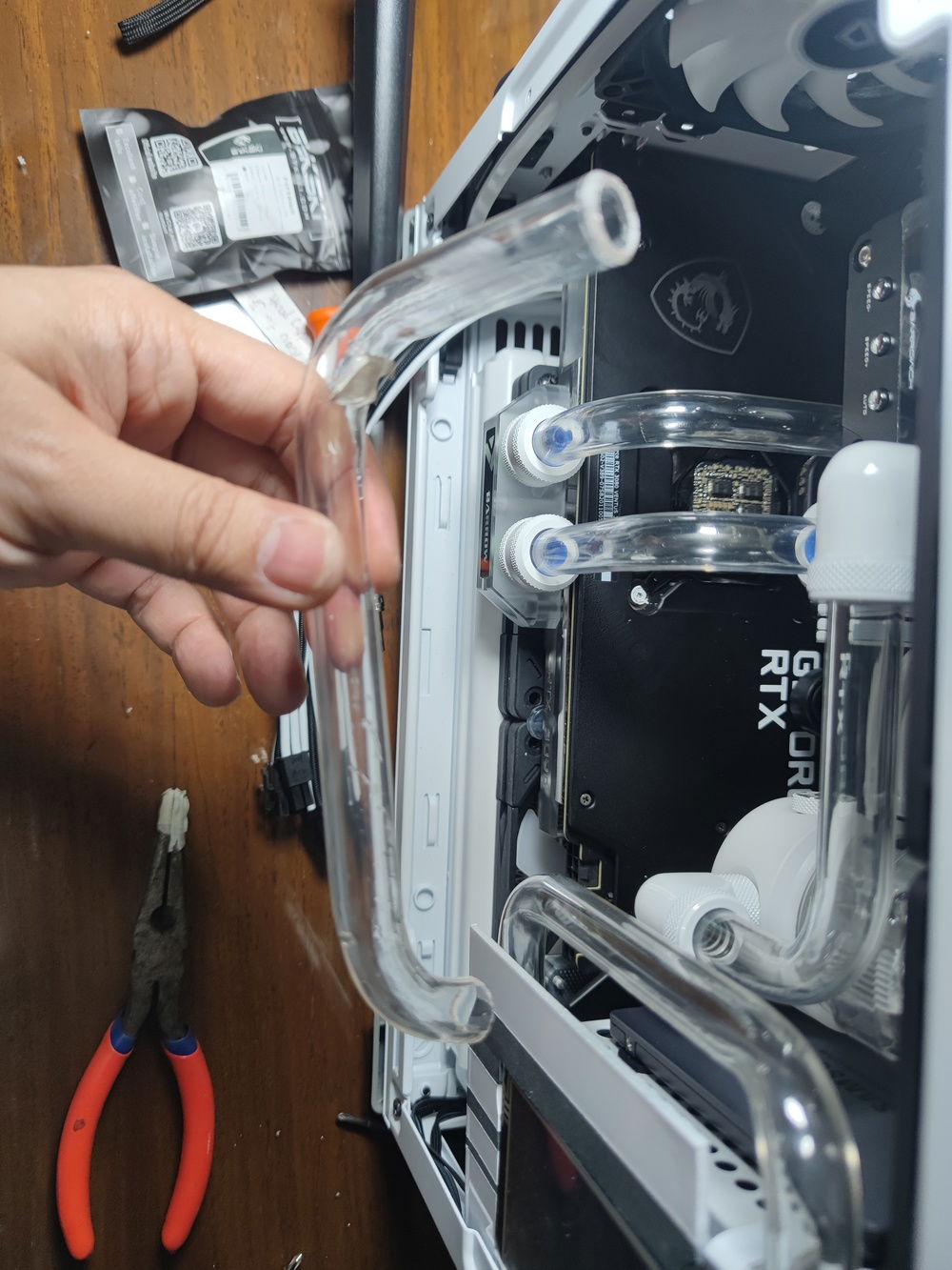
I dreaded re-bending this most complex tube in the build, but it turned out ok after the experience I gained during the process.
The replacement tube had a longer straight end and I made sure not to over heat the tube.
It fit better than the first and best yet, did not leak.
Notice the piece of hard plastic below the fitting? This is the minimum needed to avoid serious accidents. Not sure if it will help, but short of using some plumbing sealant, it's the best I can do.
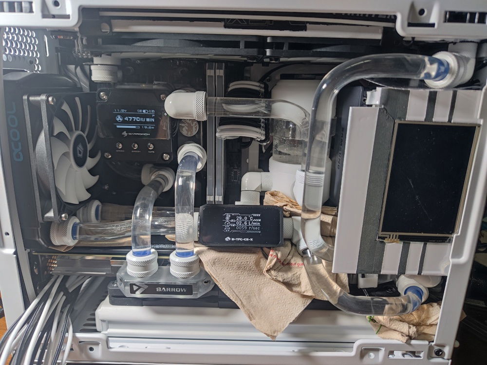
It was a relief getting the water to start moving. each fill up of the reservoir needed 5 to 10 minutes of lifting the whole PC and then tilting, dangling, upending the case for the bubbles to collect and water to move from one component to another.
This piece of plastic was cut to size to sit on top of the GPU backplate, protecting it from small drips from any of the components above it
Startup and installation.
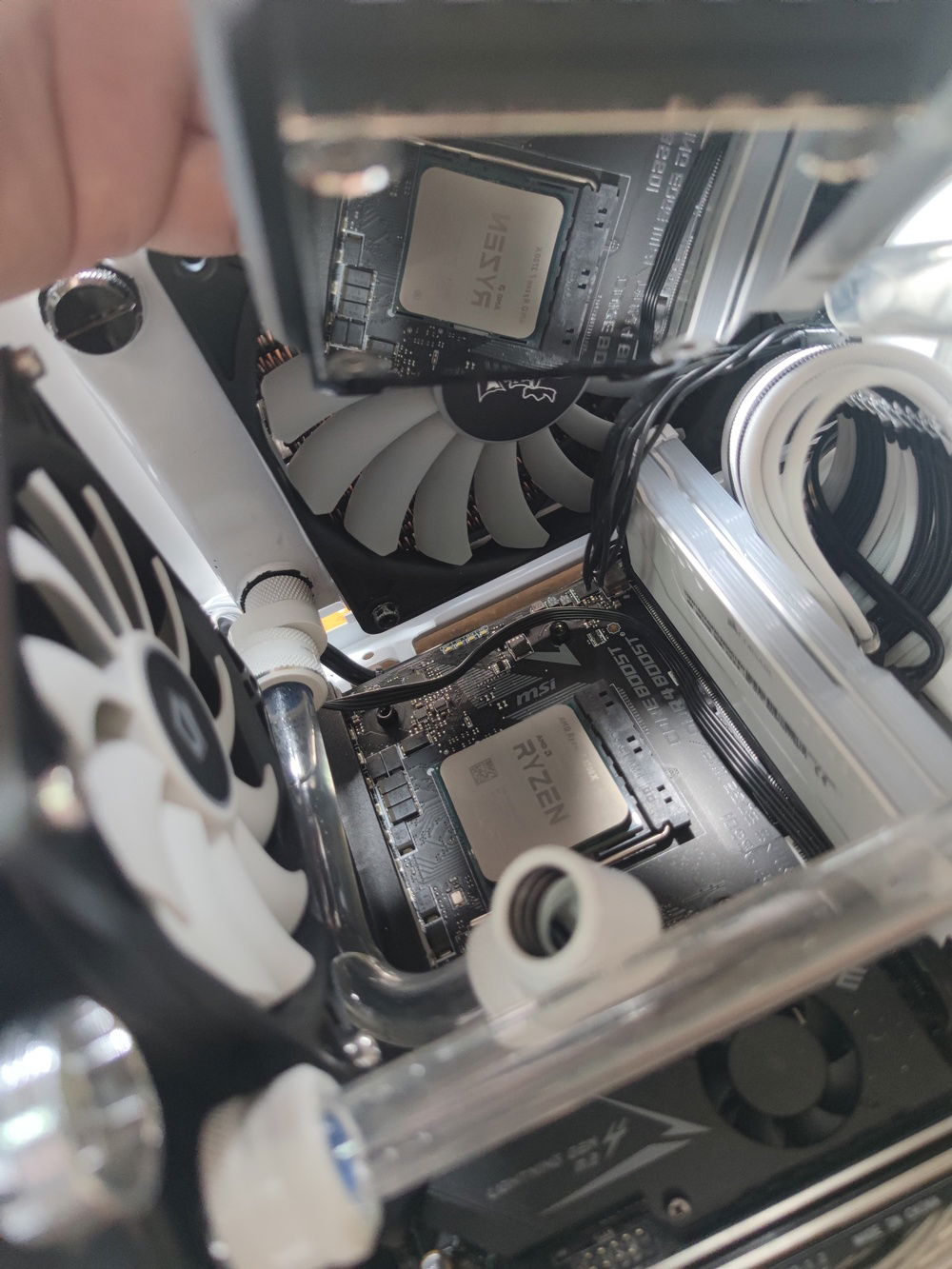
The offset fitting and tubing was skewed left until I reseated the CPU block/pump combo.
This was all the clearance I had to work with when I was turning the fittings and/or turning the screws.
Something as simple as fixing a screw required a mastery in finger gymnastics.
I chose the cooling components based on cooling performance, so I naturally ended up with the excellent Hardware Labs Nemesis series.
While not exactly slim, at 29.6mm thich, it was slim enough to be able to fit high performance 15mm thich fans from Noctua on top and still clear the GPU water block with space to spare.
A view with the GPU removed. The PSU cables can be seen here hiding behind the motherboard and support structure of the case.
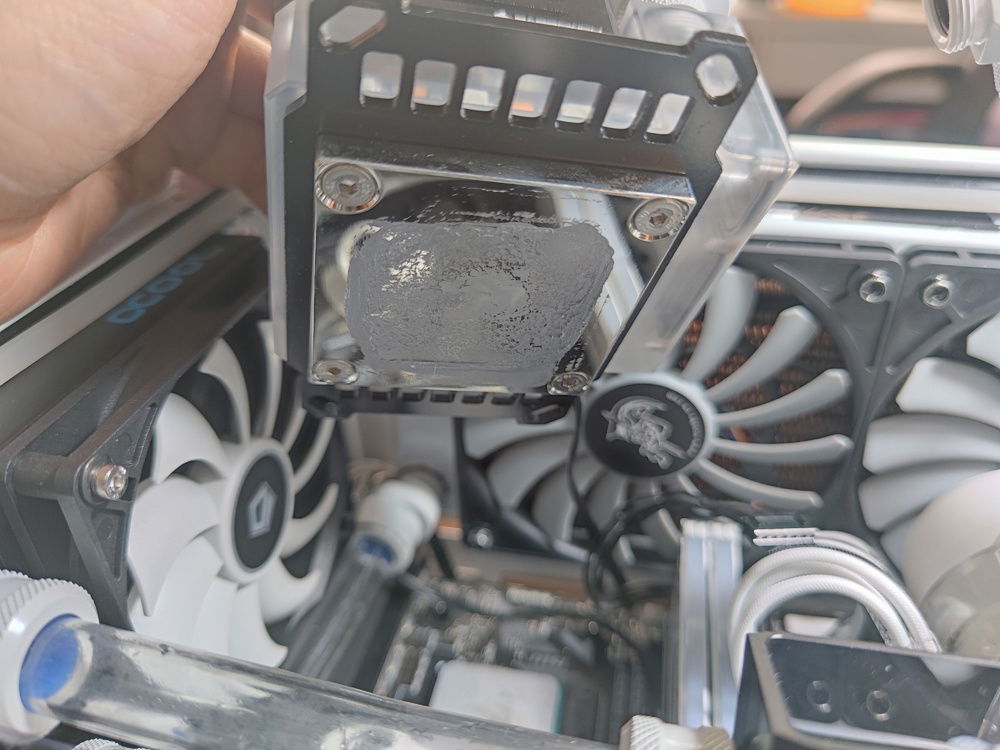
.. and cleaning the block.
Putting things back together was easier with all of the cables out of the way and the external fans wired in and standing by.

Slotting the bottom panel onto the support post locks in the external fan cables neatly.
The RGB fans in place, ready to create that underglow.
Reseating..
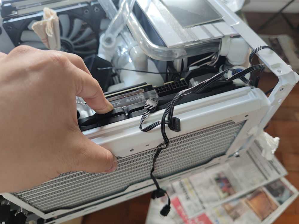
Just removing the bottom panel was nerve wracking since I had to hold up the radiator as I was removing the fan screws and water cooling tubes - without spilling any water onto components - poor planning on my part before I jumped in.
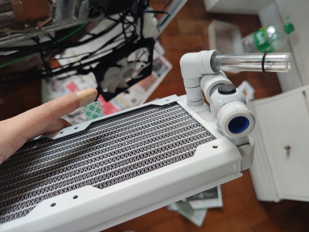
A view of the radiator with the fittings.
After removing the radiator, we see the GPU block and a mess of wires. I swear, it's arranged nicely now.
I couldn't move the case from the side position without risking water leaking all around.
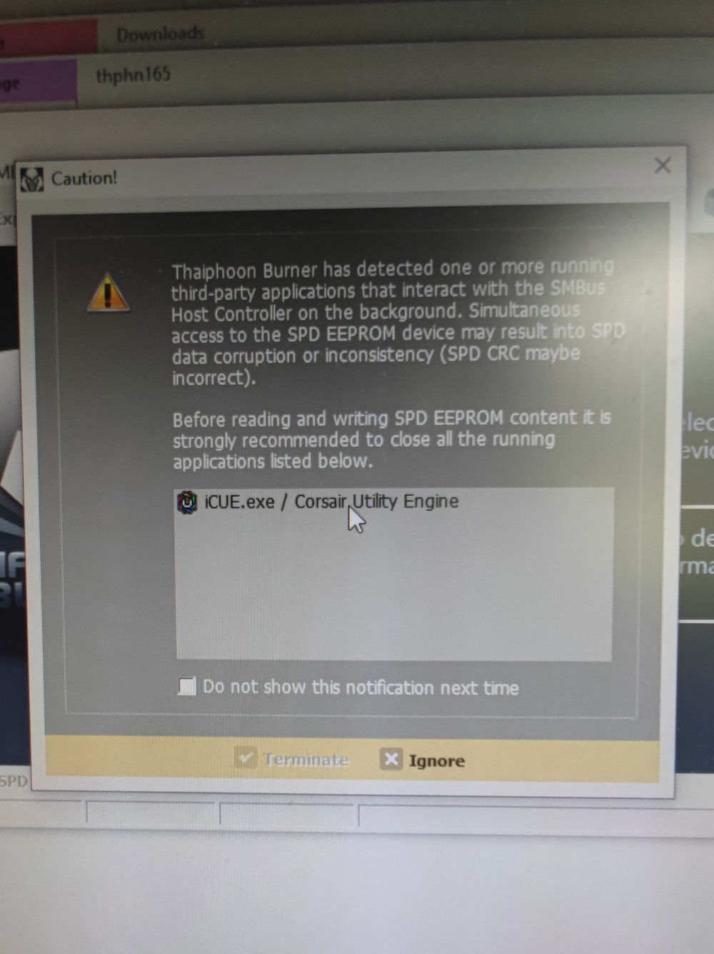
I managed to break the RGB on one stick of RAM - maybe by accidentally mixing RGB control software. This piece of software "Thaiphoon Burner" was supposed to help by resetting the SPD EEPROM firmware on the stick - instead I ended up with a busted 8GB stick of RAM.
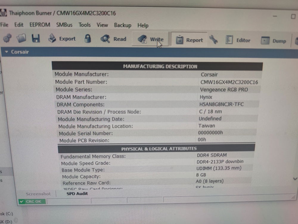
Seems correct, but I guess it wasn't.
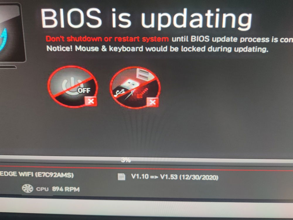
From v1.10 to v 1.53 firmware
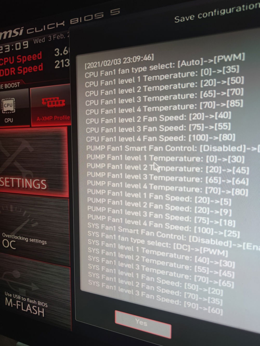
Water cooling is only quiet and effective if you do some legwork. Observed how quickly temps changed under load and adjusted the fan speeds to match.
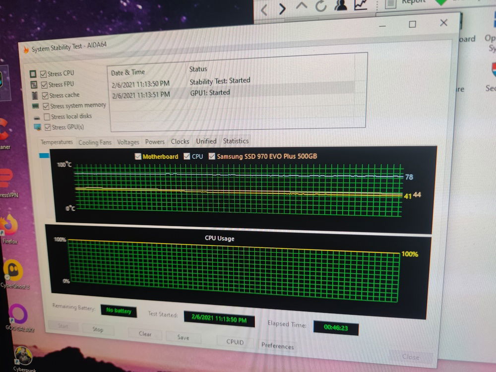
Stability test result on Aida64 stress test, but before reseating the CPU block and adjusting the overclock settings.
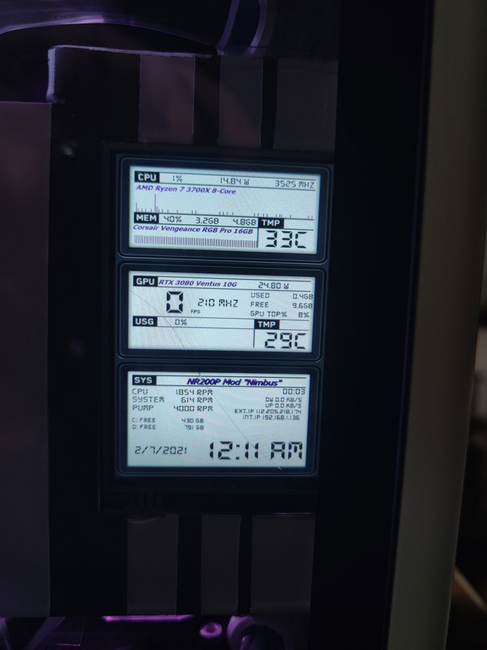
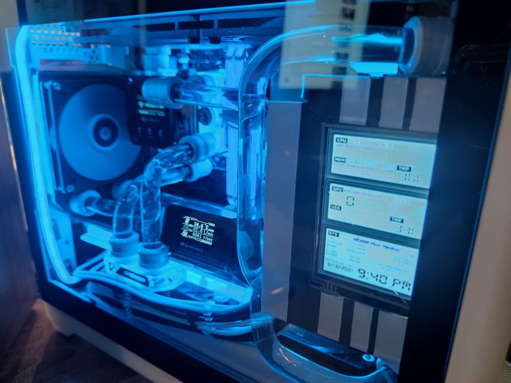
The Aida64 sensor panel enables detailed information to be displayed. This design fit the theme.
Temperatures are on idle, with an ambiant temp of 29 C.
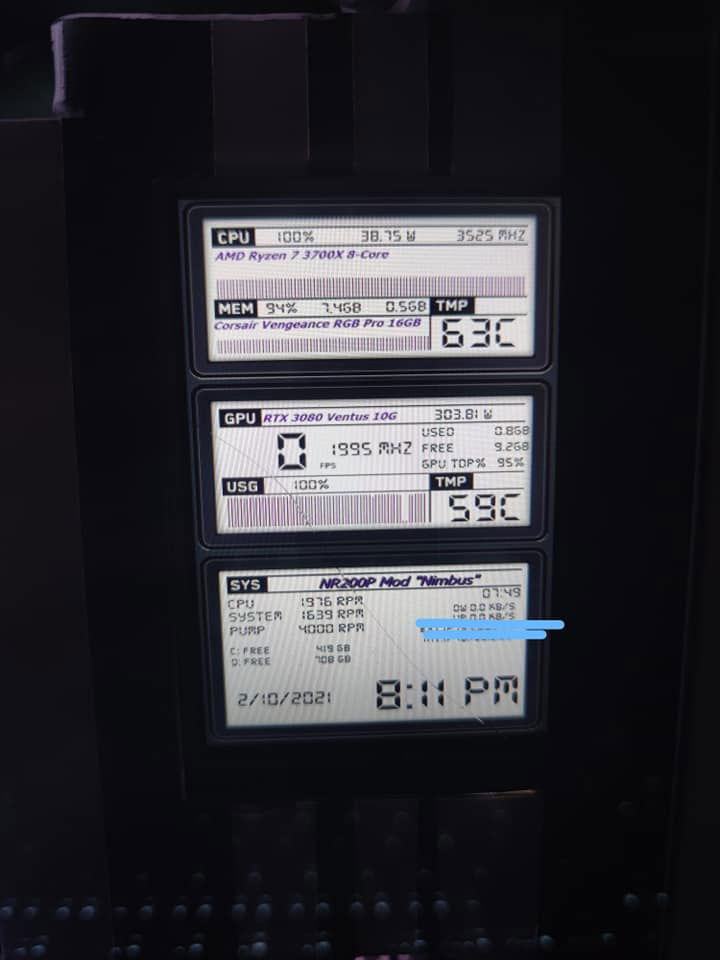
After 1 hour of Aida64 stress testing.
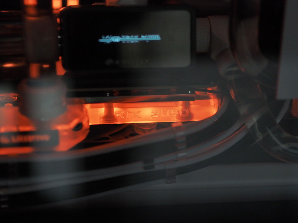
Not really a 3090, but uses the same GPU block
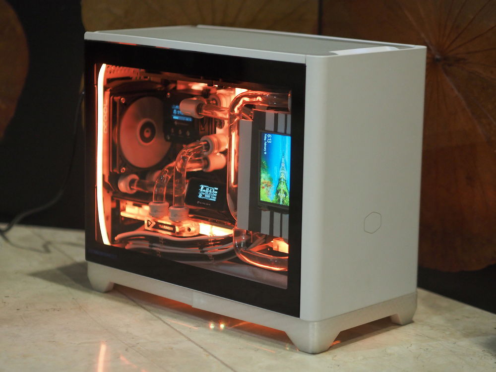
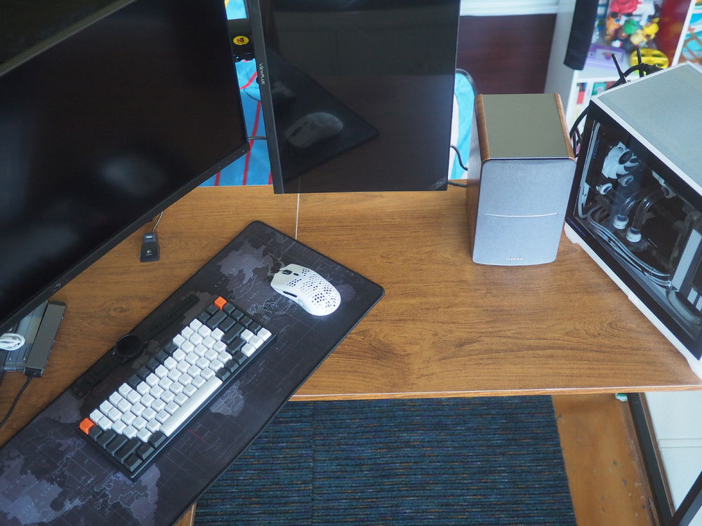
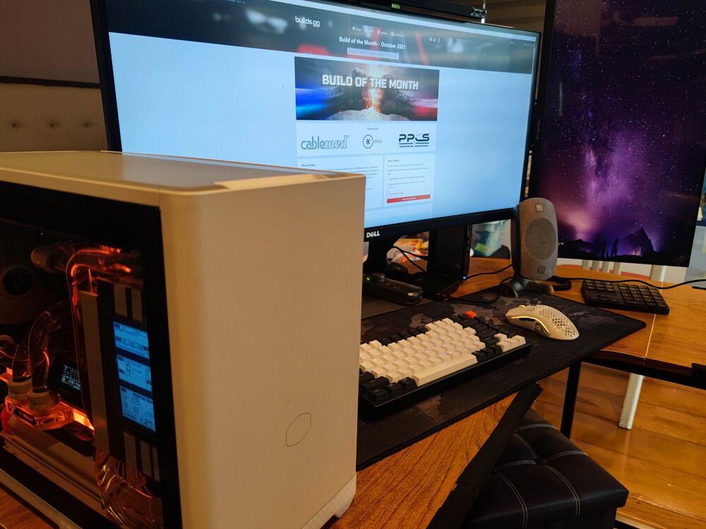
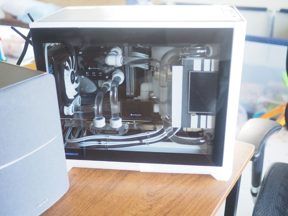
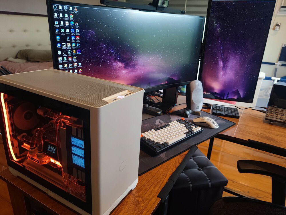
All the action happens on-screen and in-the-case. I kept the outside as stock as possible.
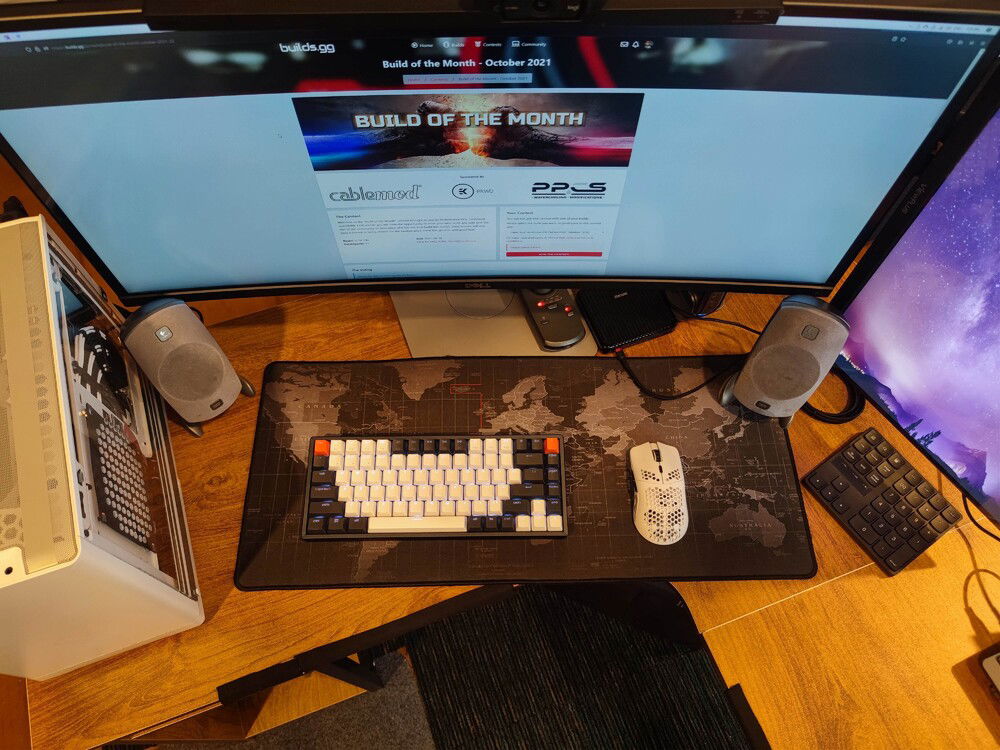
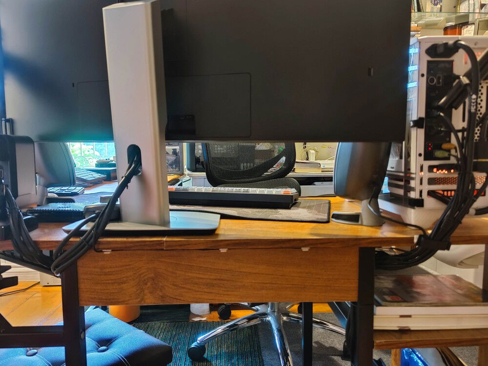
Top view of the work - game space. Speakers were reverted back to my old Logitech Z5300s. For 17 year old speakers, they really rock.
With the black and white GPU power cables gone, the scene through the side glass is much sleeker and cleaner.

Bottom view shows how I managed the cables. Tedious and time-consuming, but very worth it.

My view while on my desk.
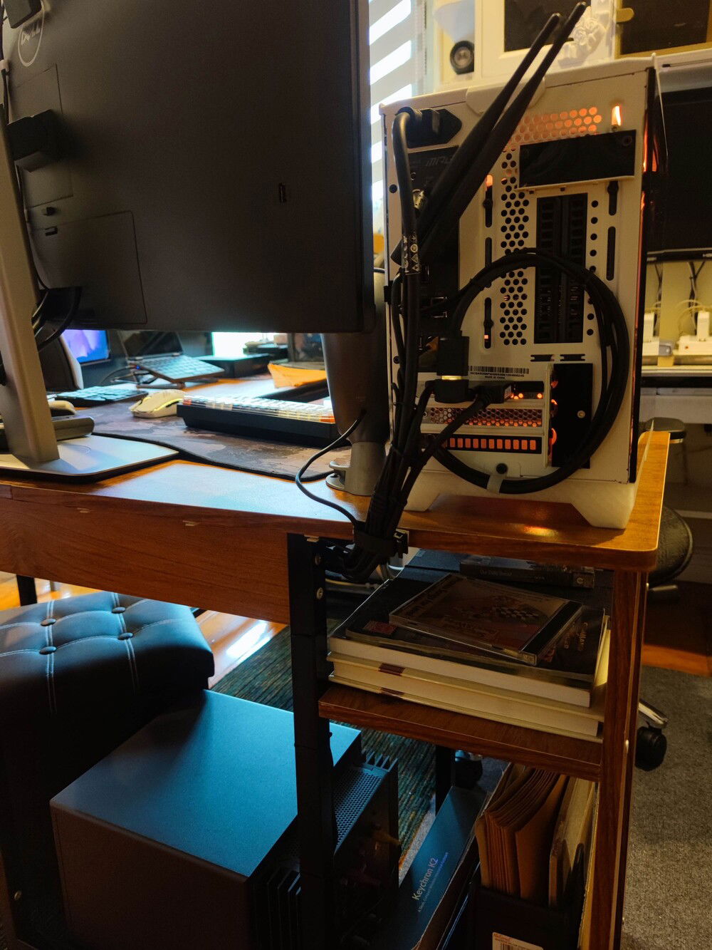
More cable management. Since I'm not up against a wall, I had to really clean things up.
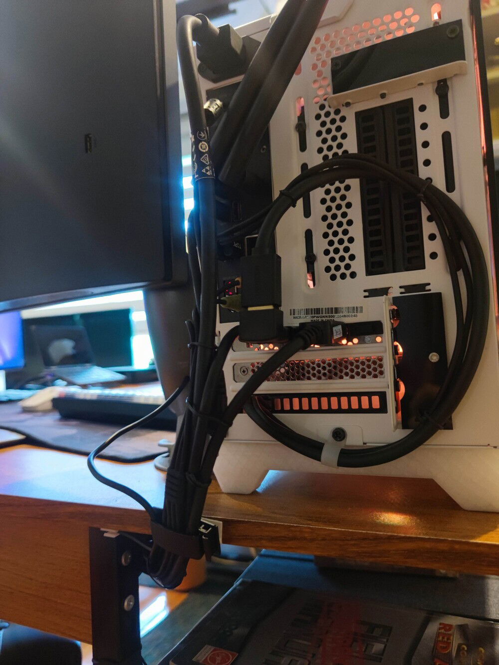
Cable management at the PC's rear. Loop is for the internal LCD.
Added a non functional Pac-Man ghost just for giggles.
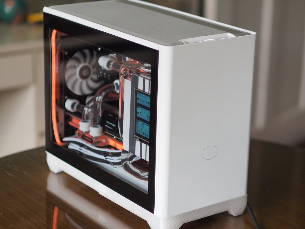
Triple Rad Hard Line ITX CM NR200P "Nimbus"
AD:
Updated: Some power lines cleaned and lined up, straightened out the lighting elements, added more storage, and included the desk setup and other components in new pics.
An ITX build with 3 radiators, hard line tubing, internal monitoring LCD, 8 fans, all wrapped in a clean and compact aesthetic.
Adding features usually only found in bigger builds, all together in a smaller space than one would expect. The Nimbus build was started to help me find out how flexible my fingers can be and how many screws and nuts I can lose behind the motherboard.
Oh, please skip to the last few pics, or access "Final Build" in the Updates/Log for the completed build if you don't care for in-progress pics.
Color(s): Black White
RGB Lighting? Yes
Theme: Case Mod
Cooling: Custom Liquid Cooling
Size: Mini-ITX
Type: General Build
Contests
This build participated in 4 contests.
| Rank | Contest | Date |
|---|---|---|
| #39 | Build of the Month - October 2021 | ended |
| #2 | Build of the Month - March 2021 | ended |
| #94 | EK 10K Challenge | ended |
| #19 | SFFPC meets builds.gg Contest | ended |
Build Updates
6 Months Down the Road Update
Planning / Layout
Fabrication / Cutting Part 1 (Internal LCD / PSU Shroud)
Fabrication / Cutting Part 2 (Top radiator / side panel modification)
Fabrication / Cutting Part 3 (Rear Panel & Miscellaneous cuts and mods)
Hard Line Water Coooling Loop and Testing
Maintenance / Horror pictures
Software, Overclocking, Sensor Panel
Final Build
Hardware
CPU
$ 278.99
Motherboard
$ 712.49
Memory
$ 456.00
Graphics
Storage
$ 148.99
Storage
$ 578.35
Case
Case Fan
Case Fan
$ 59.90
Case Fan
$ 44.85
Case Fan
$ 28.00
Cooling
Cooling
Cooling
Cooling
$ 23.99
Cooling
Cooling
$ 147.59
CableMod
Accessories
Accessories
$ 69.95
Accessories
$ 994.97
Accessories
$ 21.99
Mouse
$ 79.99
Chair
Approved by: