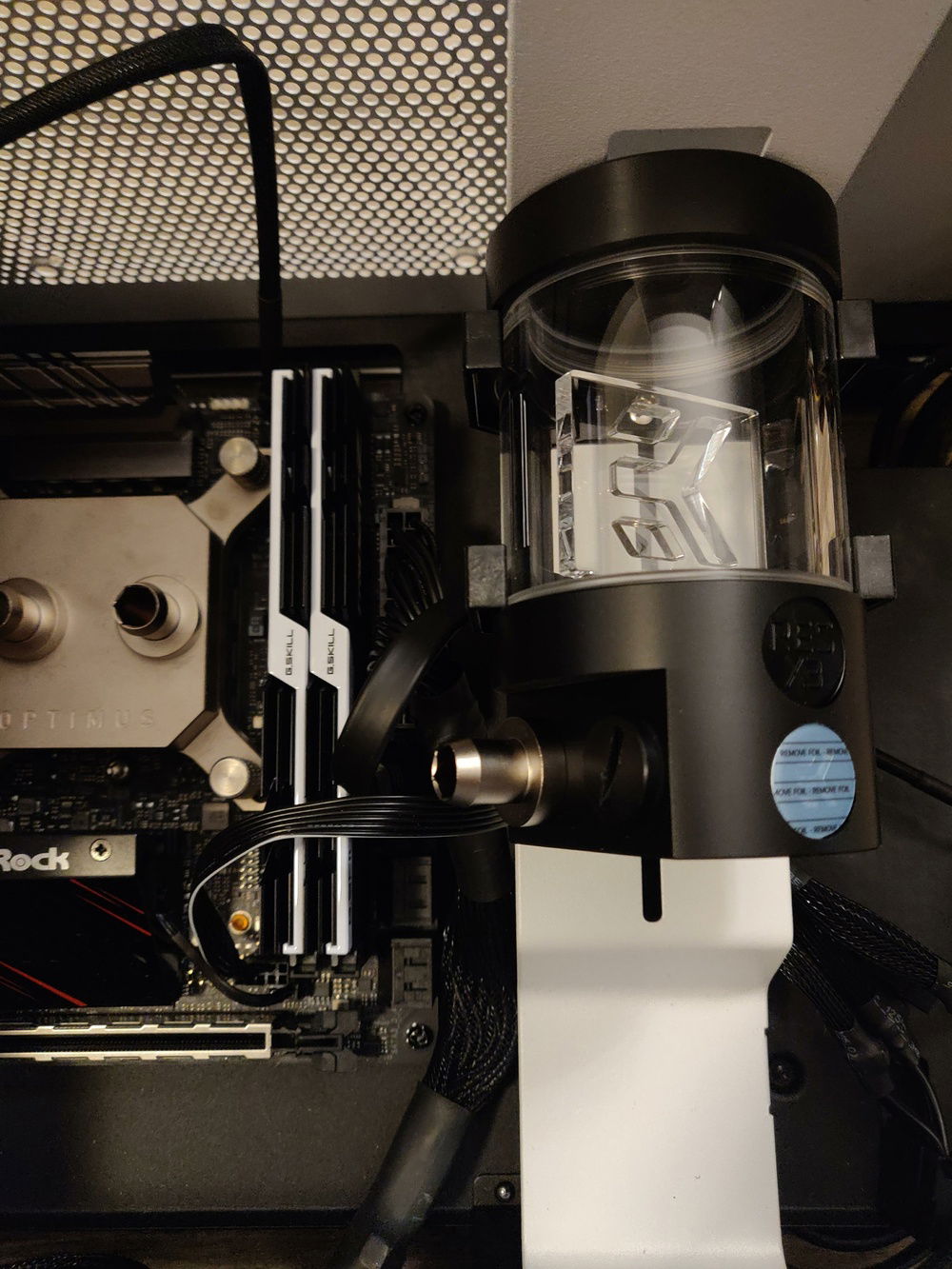
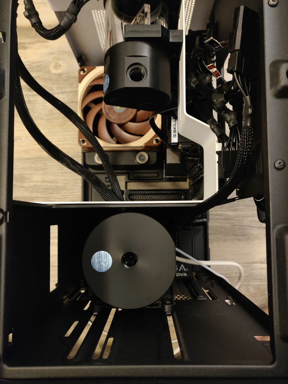
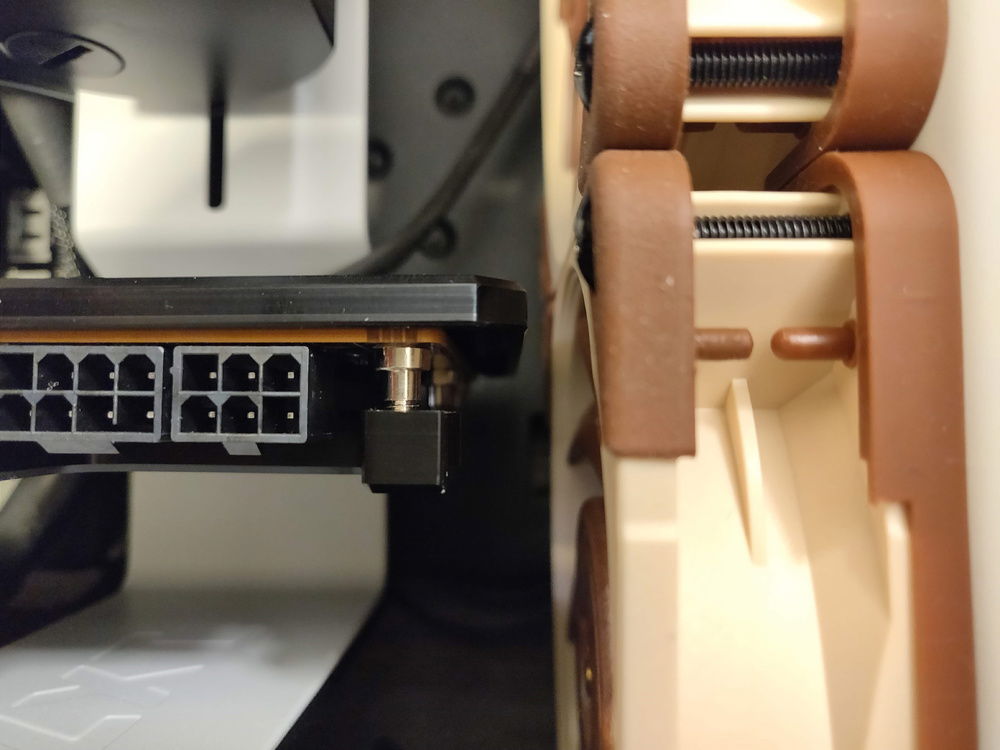
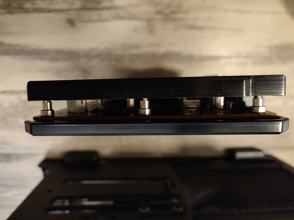
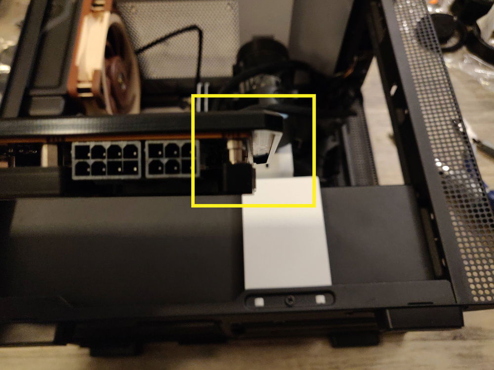
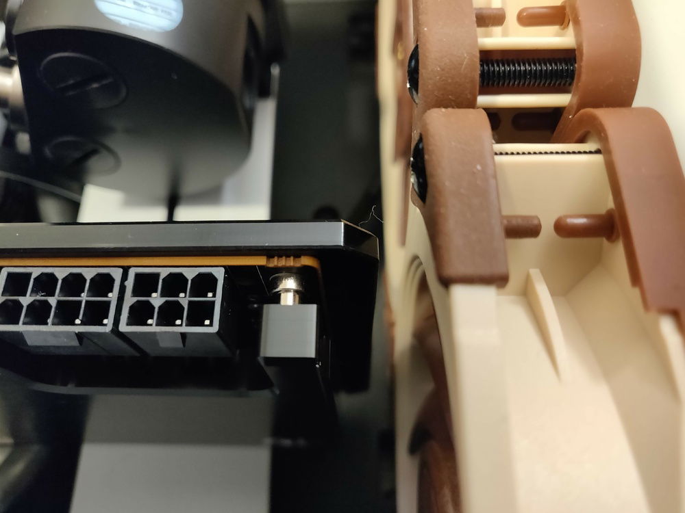
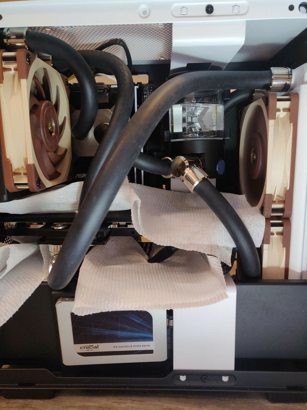
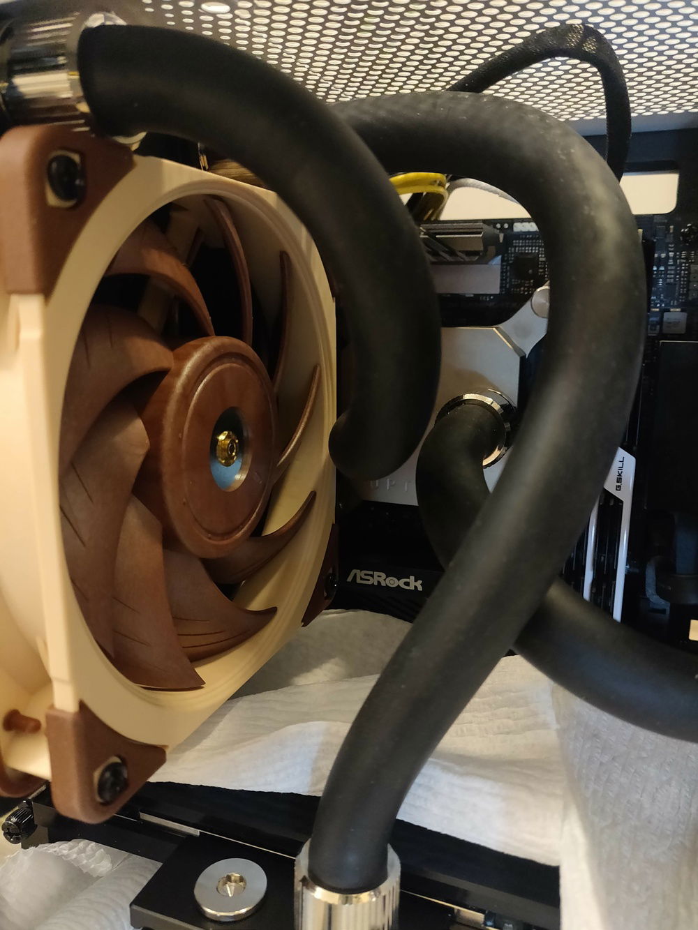
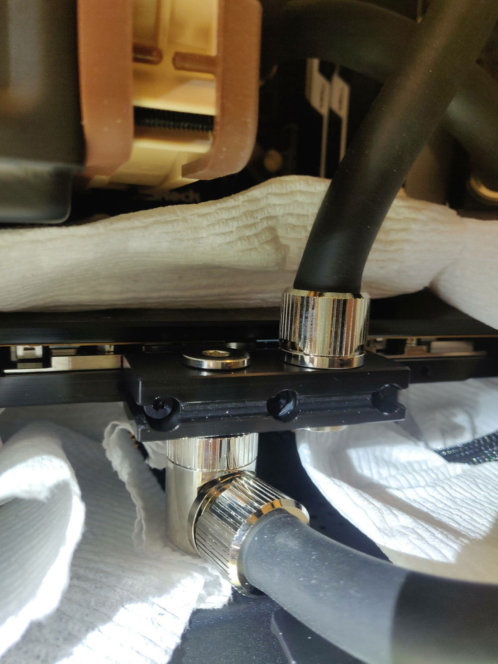
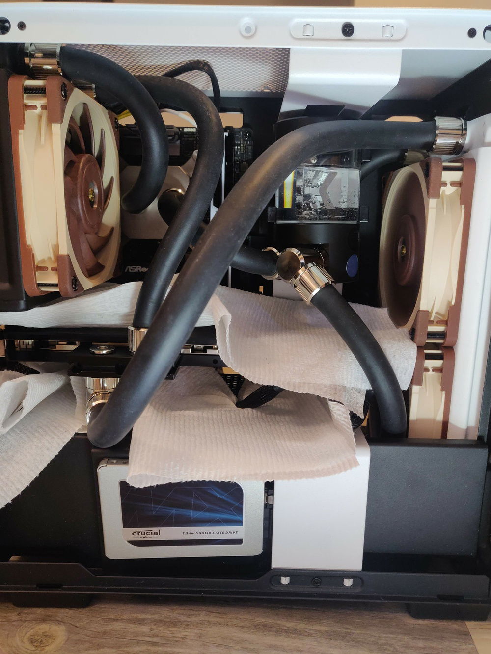
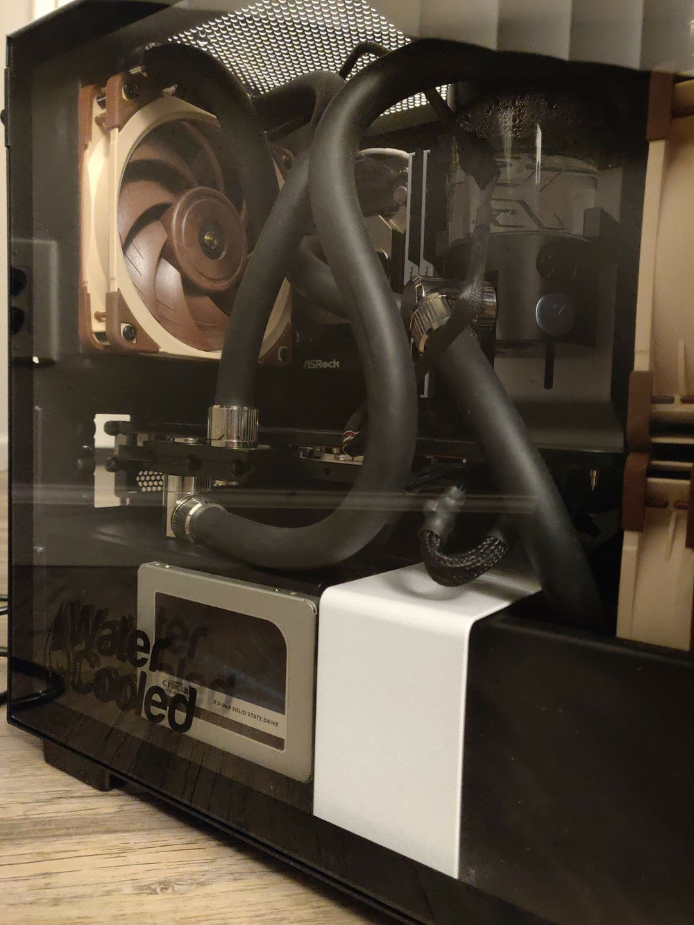
AMD Ryzen / Radeon water cooled in a NZXT H210 using Optimus Signature v2
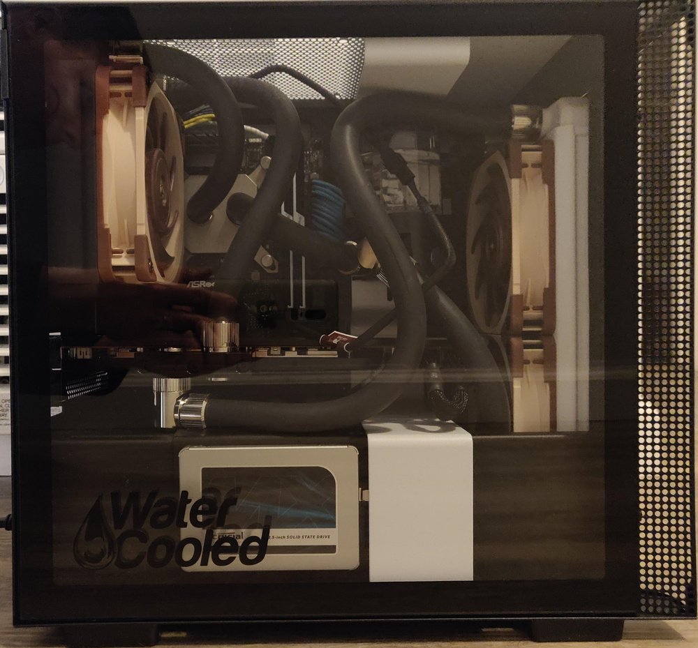
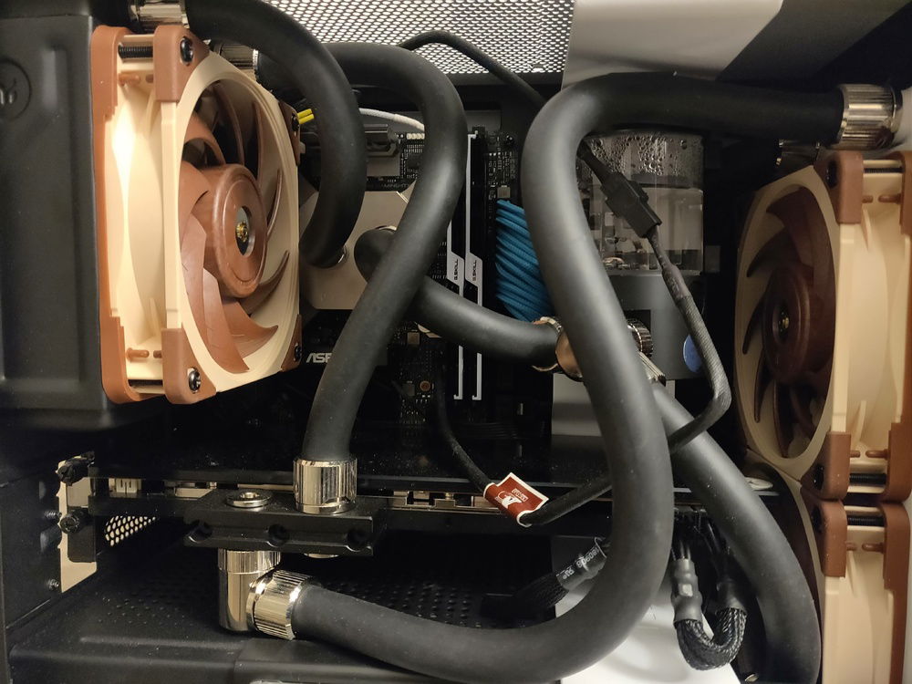
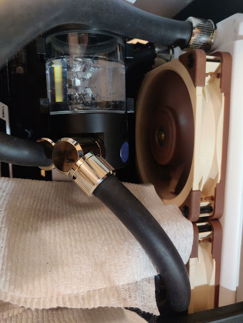
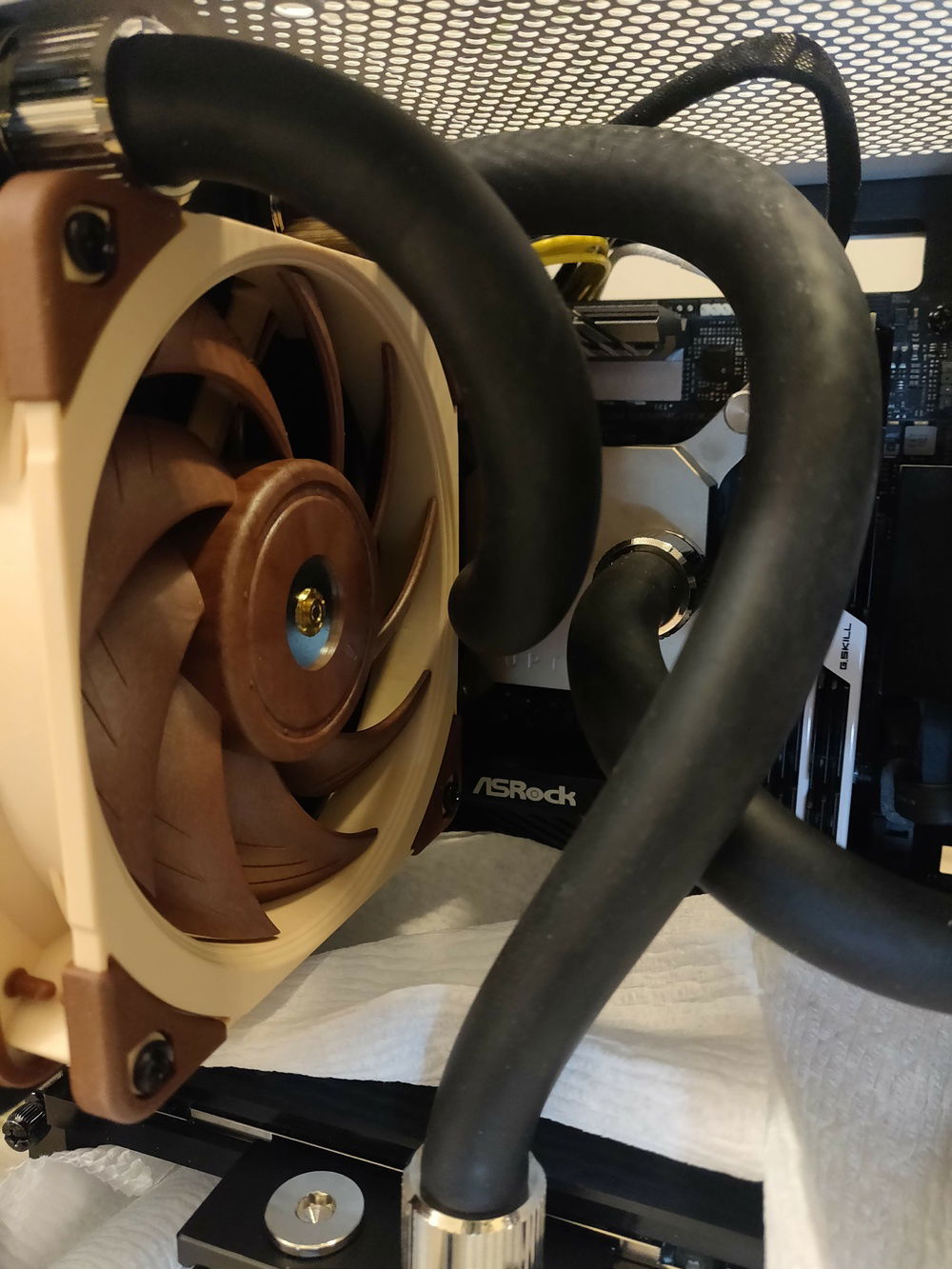
This is a water cool build within a ITX case featuring the NZXT H210 and Optimus Signature v2. This was my first water cool build ever. I didn't try to color match anything so it looks like a mess, but I'm okay with that. ![Emoji]()
What I learned from making this build:
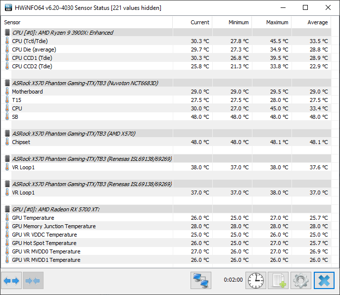
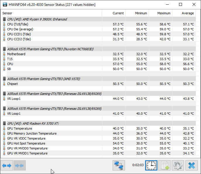
Check out pictures three through five in the slideshow for thermal information.
What I learned from making this build:
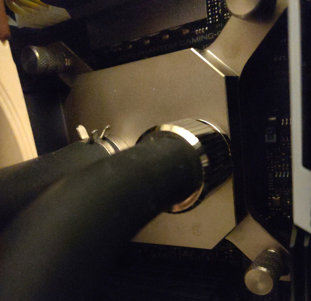
- Soft tubing will slowly rotate while you are rotating the compression fitting cap.
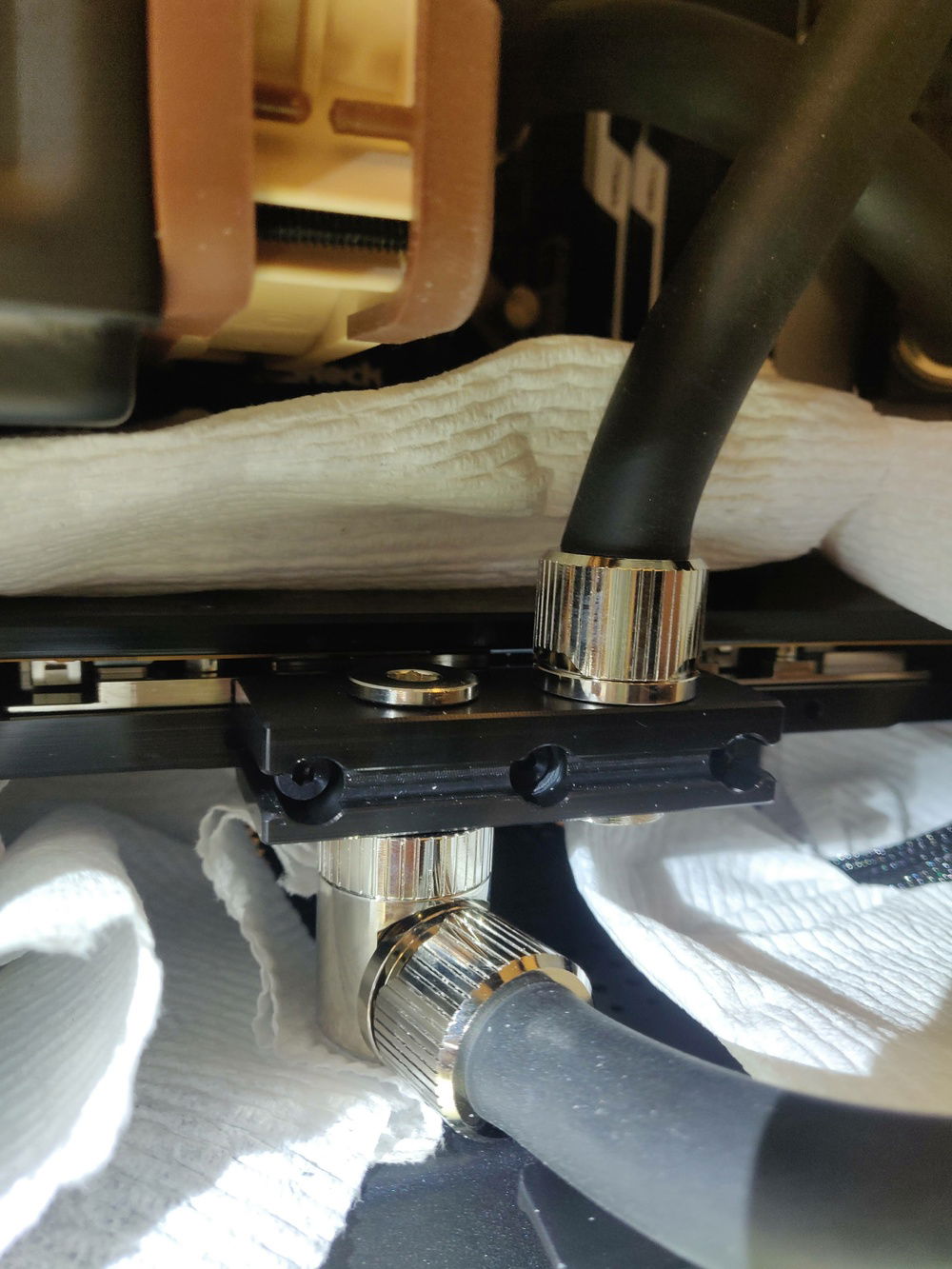
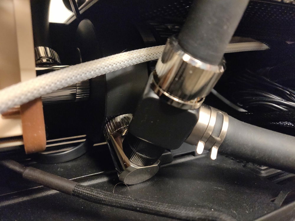
- Soft tubing does not have great flexibility. The more of an angle you try to compress the tubing the more each end of the tubing exerts sideways pressure on its fitting. I intentionally kept many tubing pieces longer than would appear necessary specifically to keep pressure on the fittings as low as possible.
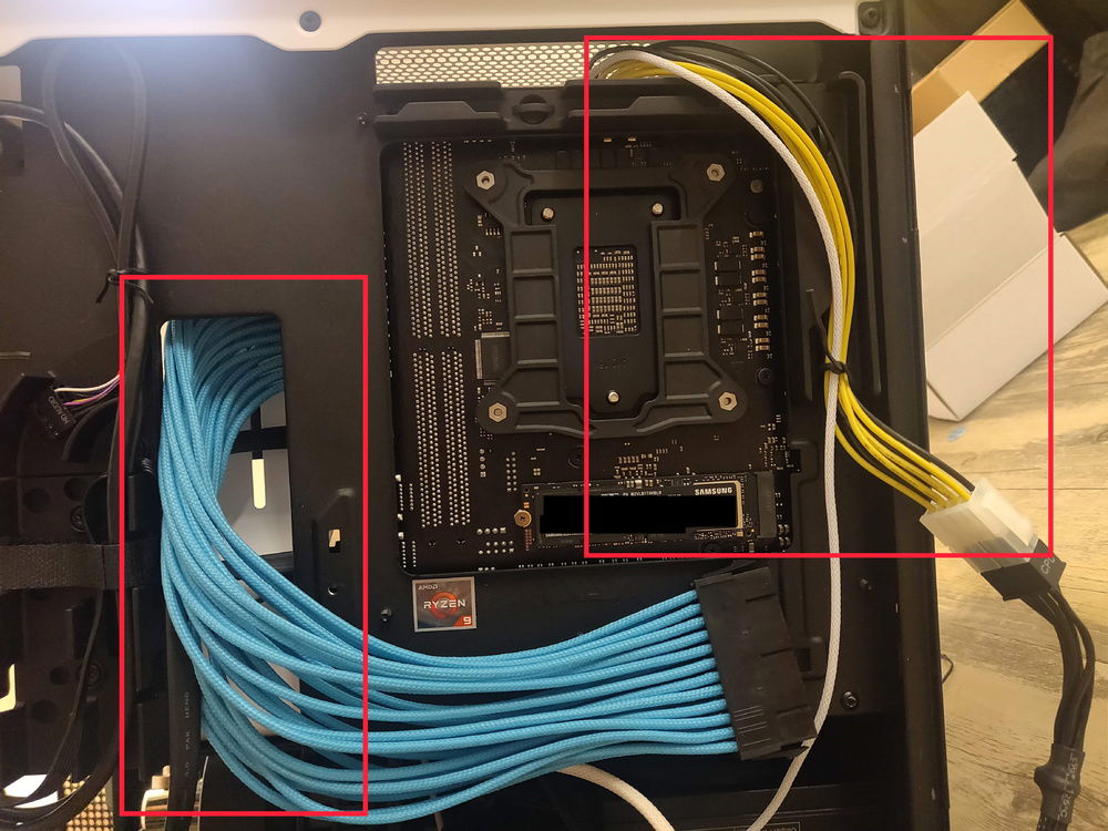
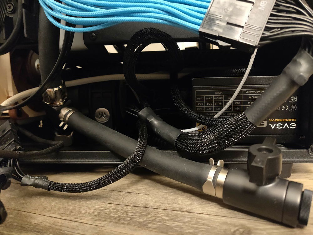
- The cables that come with modular PSUs are way too short.
- Water cooling is expensive! I had to replace parts I originally bought after discovering they wouldn't fit in this smaller case because the parts manufacturers don't provide all of the measurements I had needed.
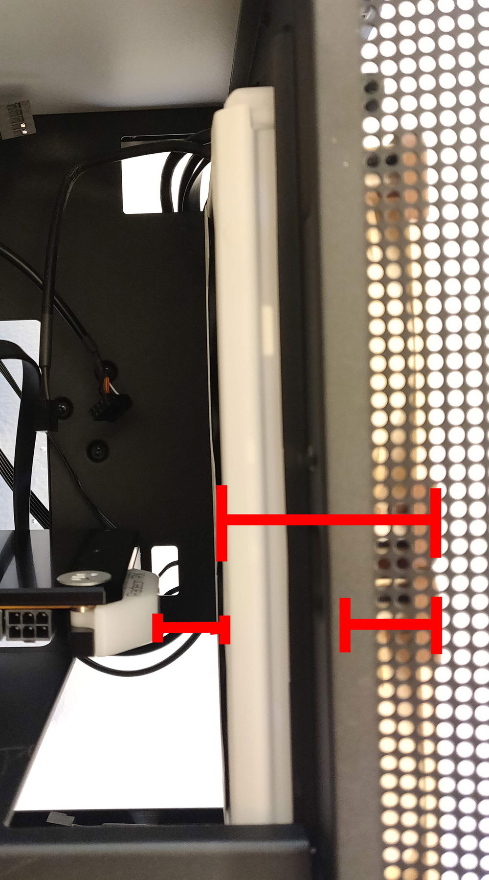
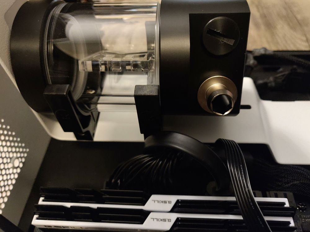
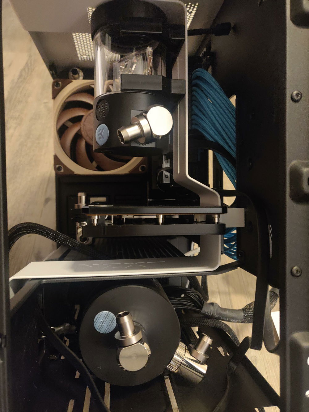
- The height of a pump and reservoir combo unit given by the manufacturer will be about 3 millimeters taller in real life if the pump cables come out the bottom of the pump.
Check out pictures three through five in the slideshow for thermal information.
Color(s): Black White
RGB Lighting? No
Theme: none
Cooling: Custom Liquid Cooling
Size: Mini-ITX
Type: General Build
Build Updates
Filling the reservoir
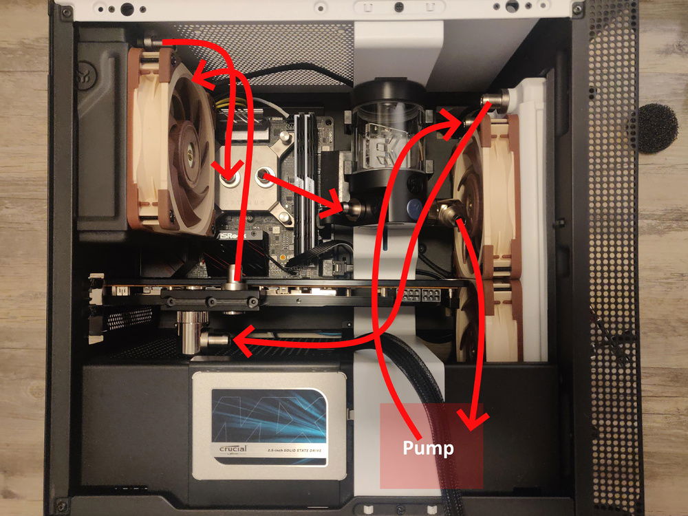
Tubing, filling, and finishing
Tubing mapped out and PSU extensions installed
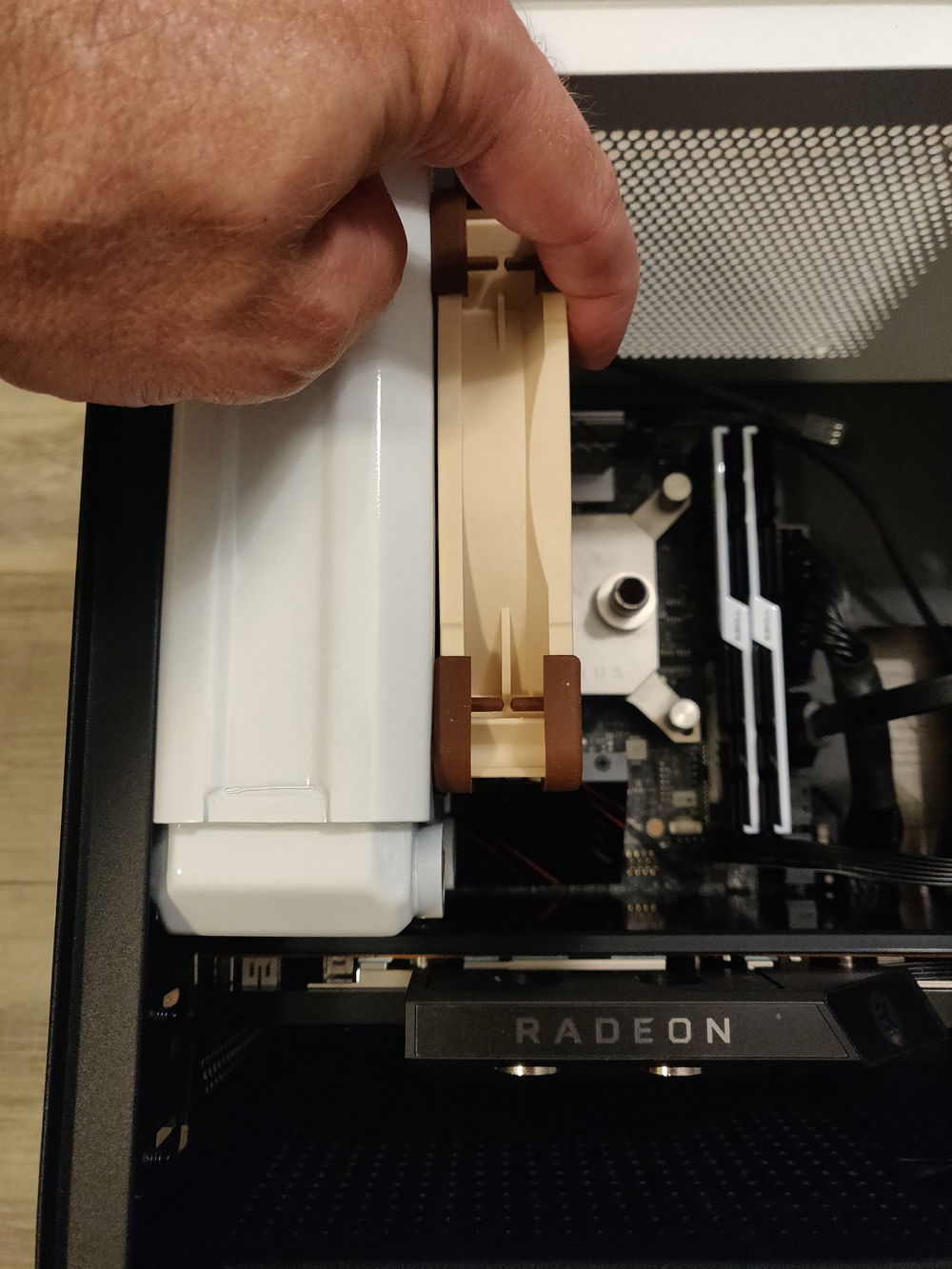
Adjusting the 240mm radiator placement
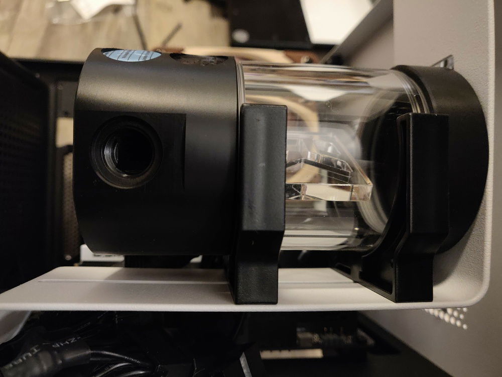
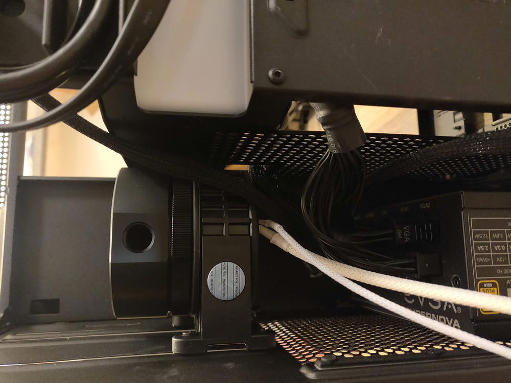
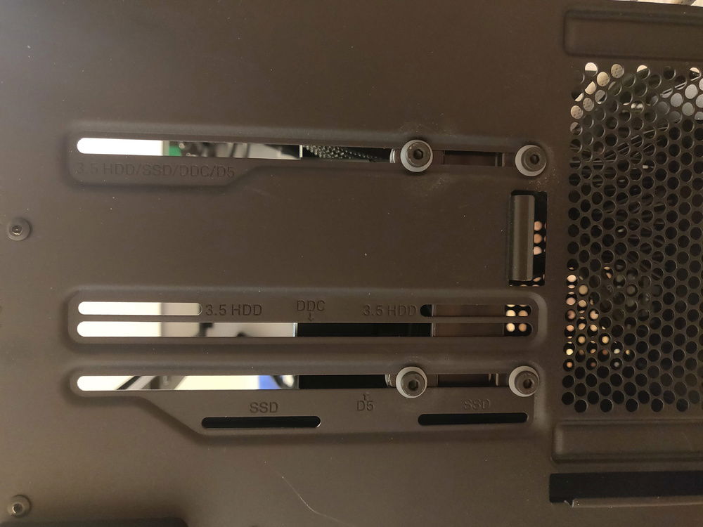
Reservoir and Pump Installation
Installing the 120mm radiator
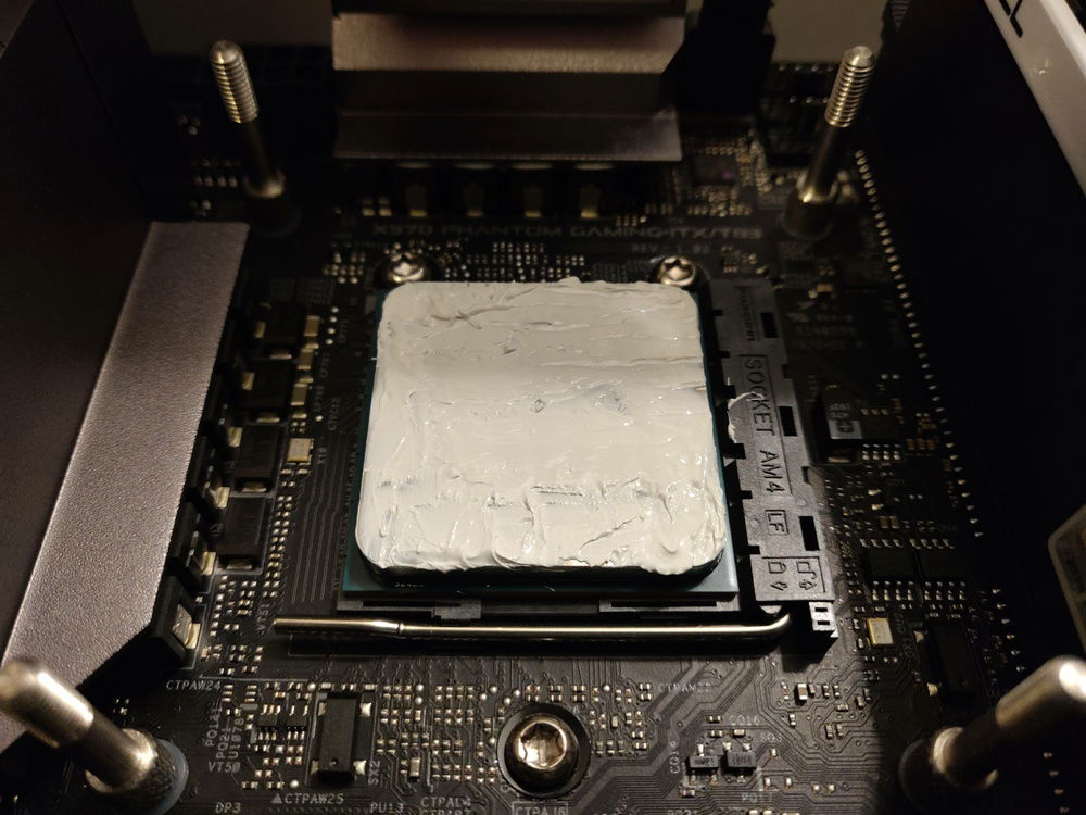
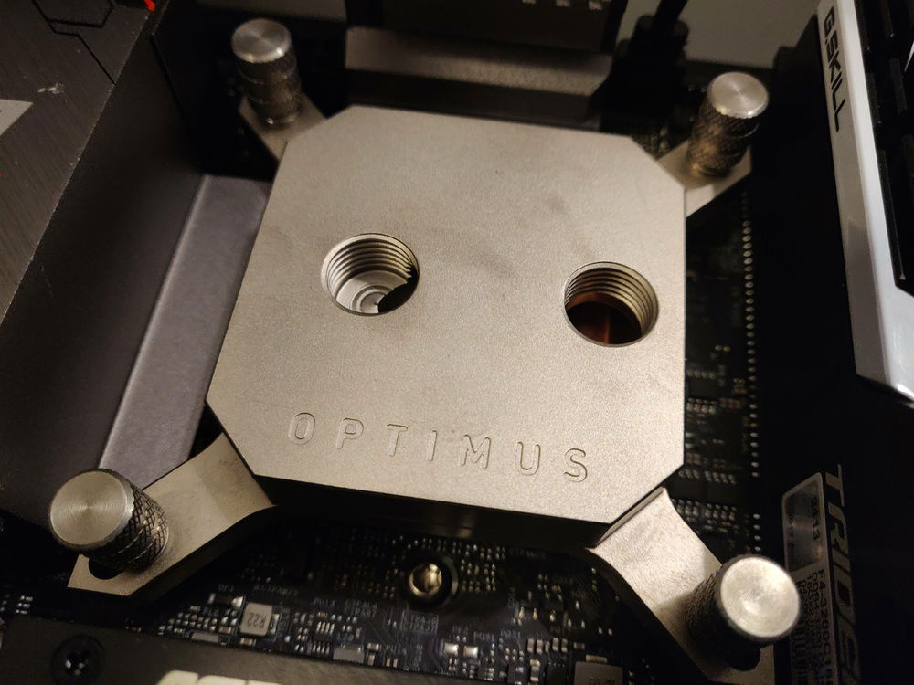
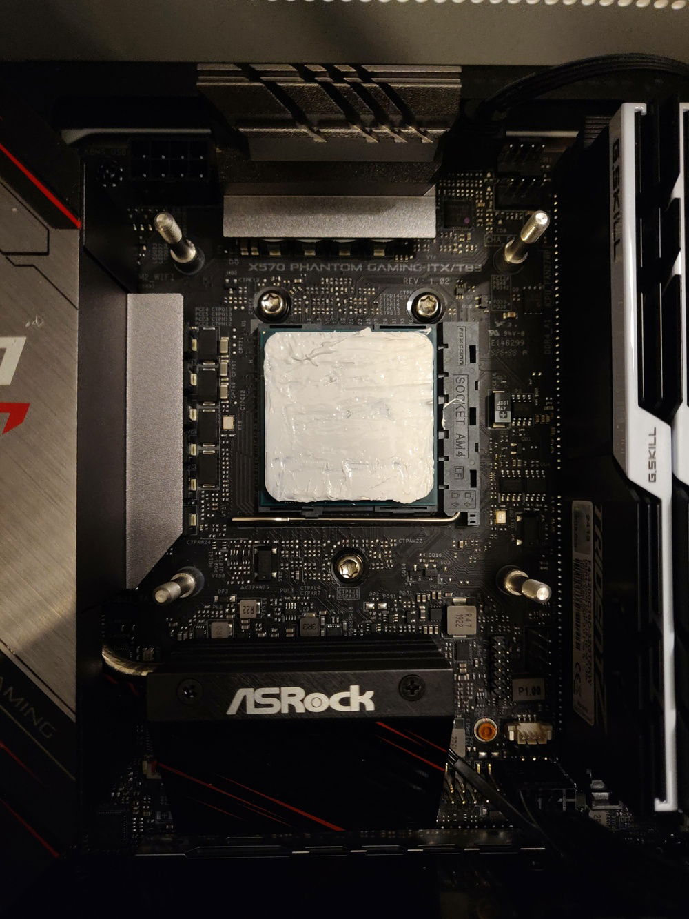
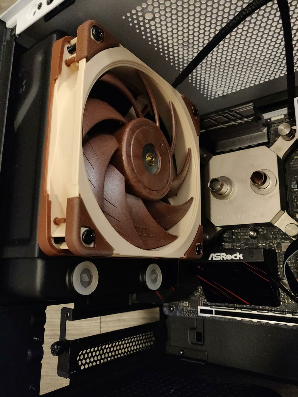
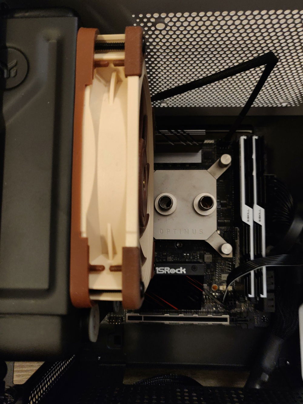
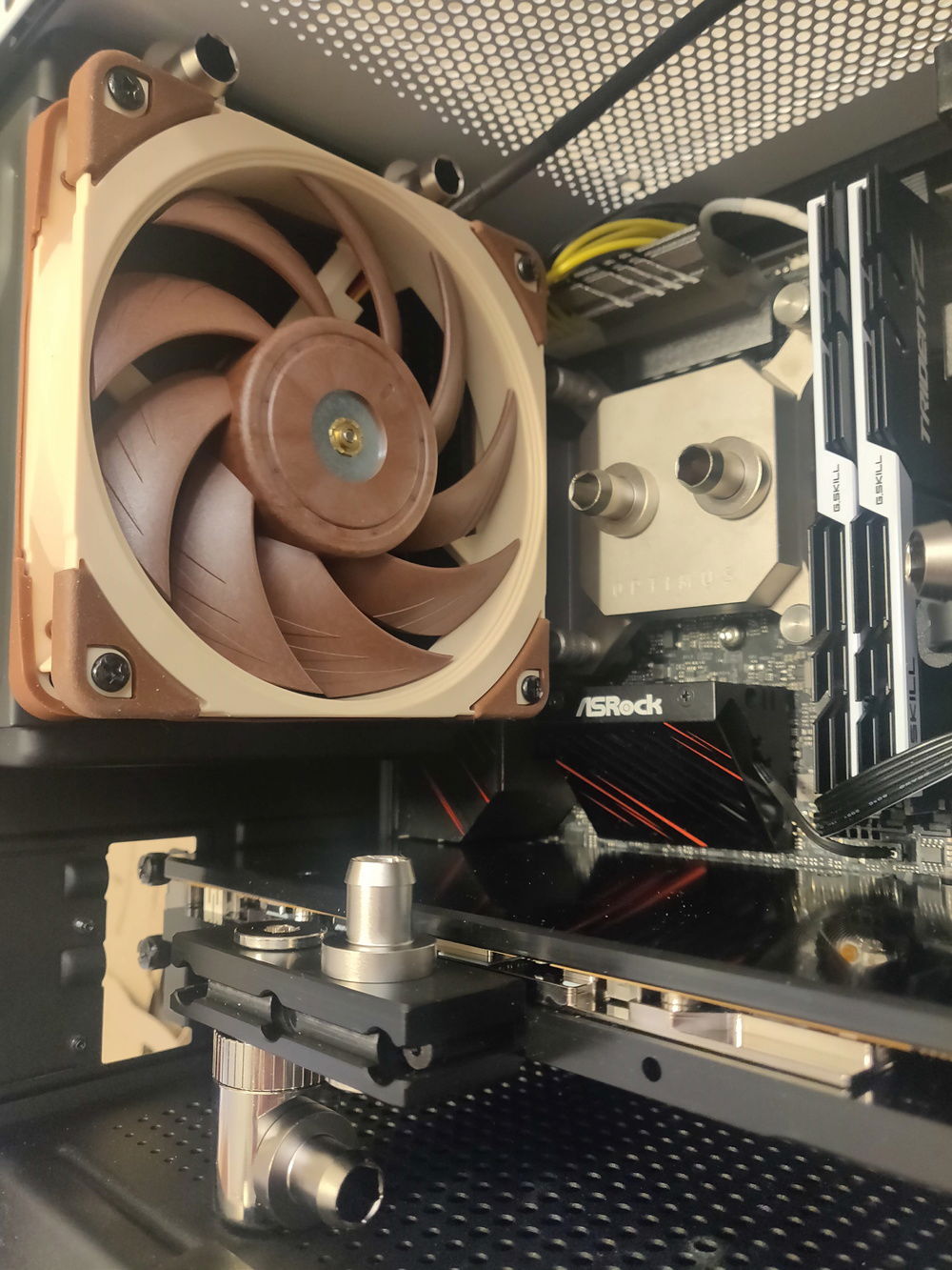
CPU water block installation
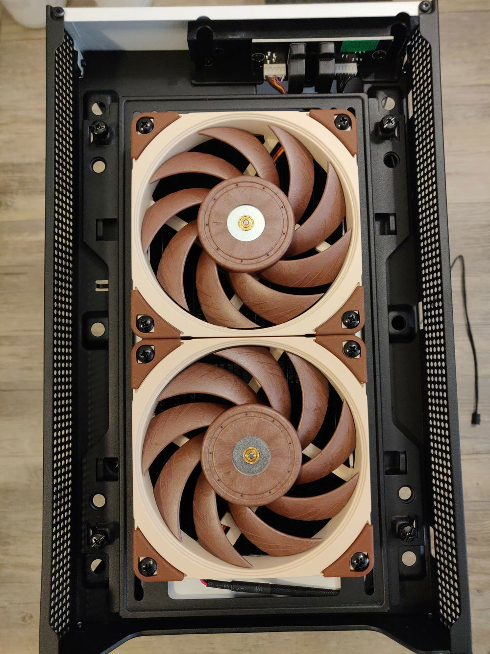
Installing the 240mm radiator
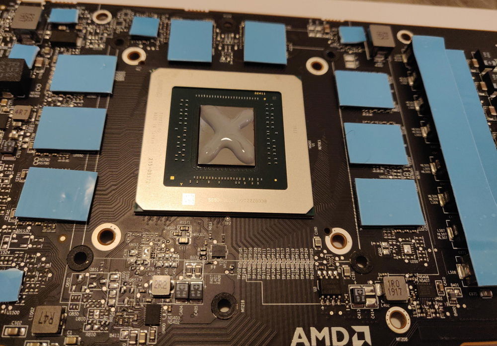
Preparing the GPU for a water block
Hardware
CPU
$ 225.00
Motherboard
$ 259.00
Memory
$ 139.99
Storage
$ 189.81
PSU
$ 299.99
Case
Case Fan
$ 34.95
Cooling
Cooling
$ 32.99
Cooling
Cooling
$ 29.99
Cooling
Cooling
$ 34.29
Cooling
Cooling
$ 129.42
Cooling
$ 149.99
Cooling
Cooling
Approved by:
