Mini Z Build Log
So for you that don't follow me or my page, this build was a re design and some design improvements on my mATX build in 2019/20; Project Z.
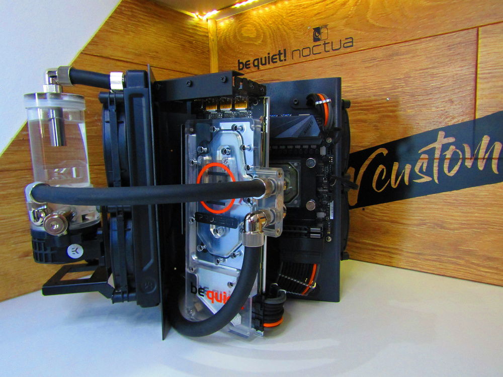
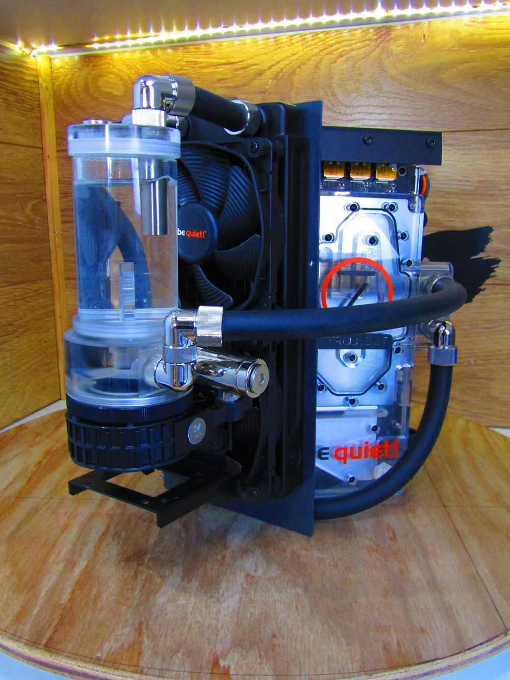
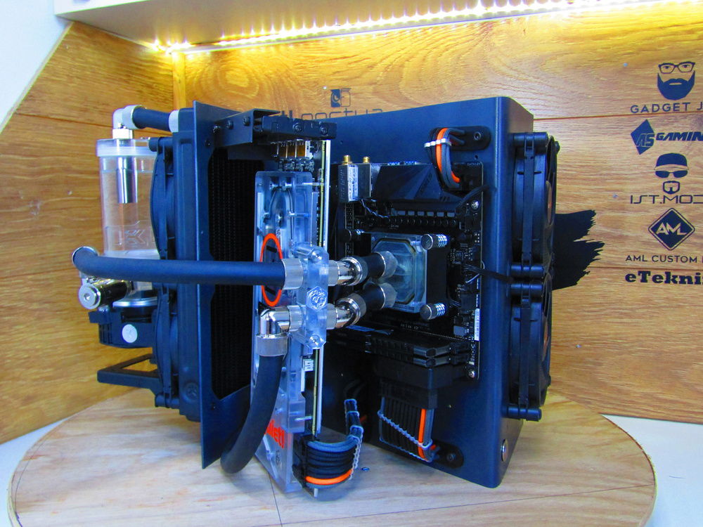
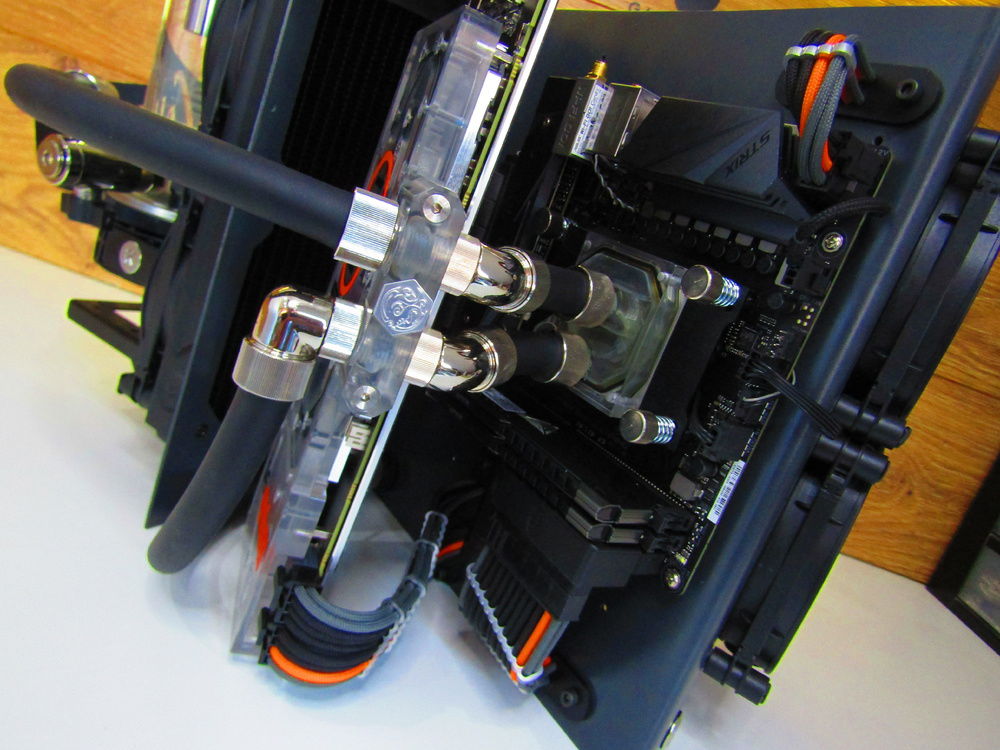
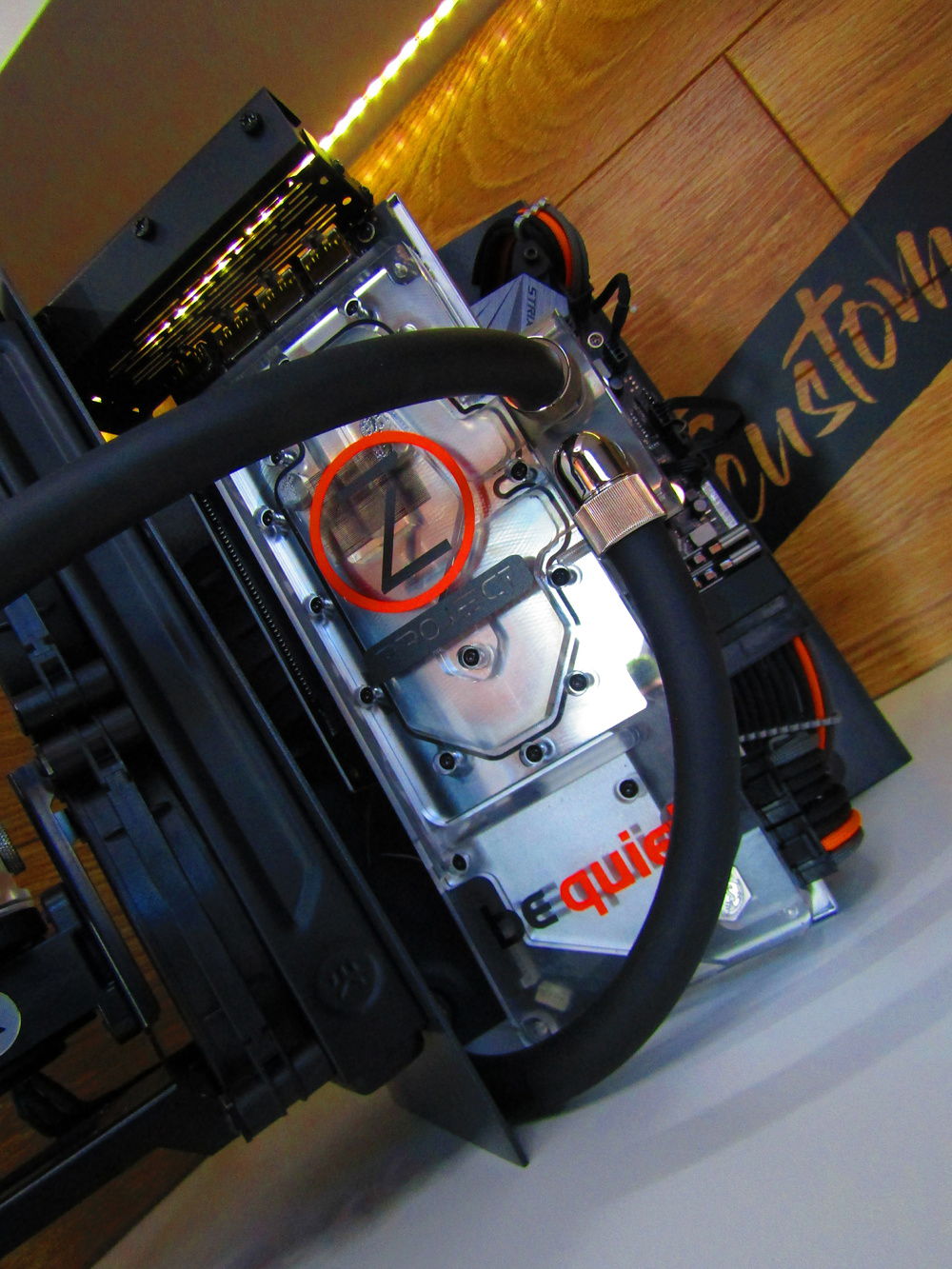
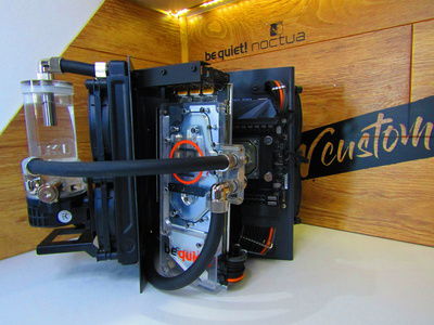
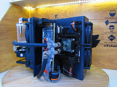
The goal was a fully watercooled ITX build as small as I could, the footprint in the end was 12” x 10” x 6” without the components.
So here’s the good stuff.
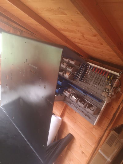
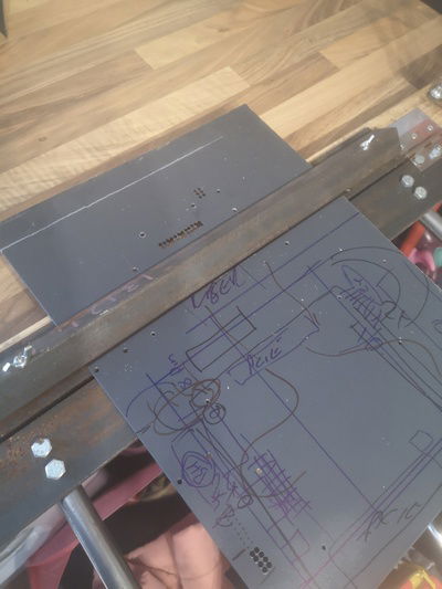
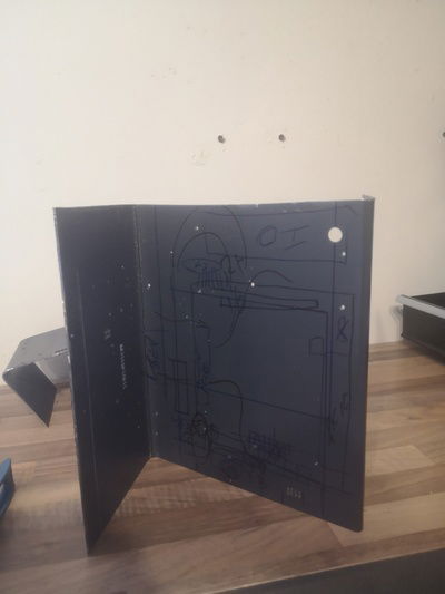
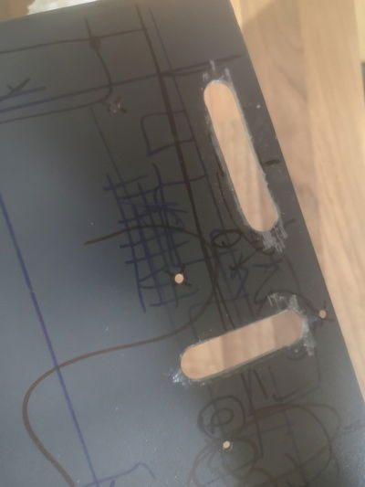
I started with the original case from Project Z, some sharpie markings and sketching marking out component sizes and various orientations with cable routes, bulkhead fittings and tubing runs.
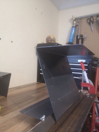
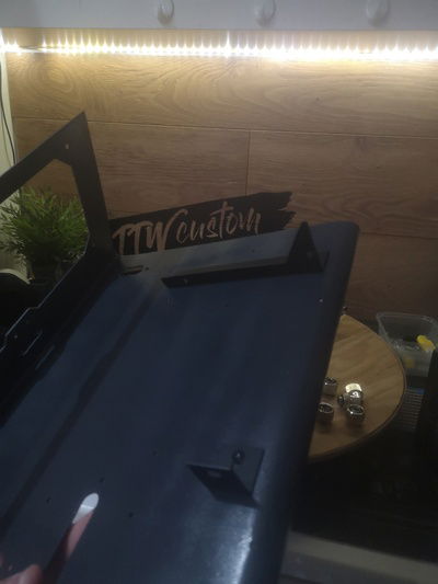
Once I was set and happy with the planning, I trimmed the case down to size, took about 6” off the side, and rotated it 90 degrees. I wanted to mount it this way, as I wanted my IO at the top this time as it was close to the desk before and made putting cables in and out tedious.
Then I removed the pre bent side, leaving as much straight material on as I could. I wanted a 6” bent tab just like the other side to mount a radiator and fans so they were symmetrical in design.
I put the steel sheet in my DIY bender, made from some thick steel and a CLC piece of timber. I did a practice bend on the scrap part, it bent like butter.
Did it in several stages, 45 degrees then as close to parallel as I could to the opposite side, teasing every degree until it was right. I used a spirit level to check this and a measuring tape.
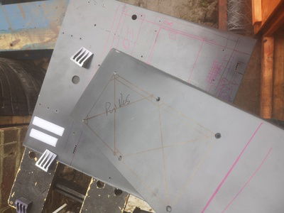
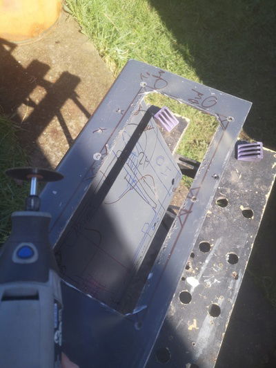
Then the grinder, dremel with cutting discs, files and sandpaper came out. I marked off some material I wanted to remove for fan air flow. In the original design I had the radiators on standoffs forcing the air to do a 90 and almost 180. I felt temps were not good and this was something I had to do.
I went for an almost hexagonal pattern for each fan, as it was 2mm steel I didn't decide to leave a partition in the middle as it had a lot of strength. Also was going to be orientated differently than my previous model which had some flex to it the other way around. Added screw holes in which to mount the radiator and fans to.
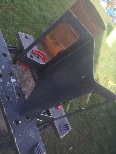
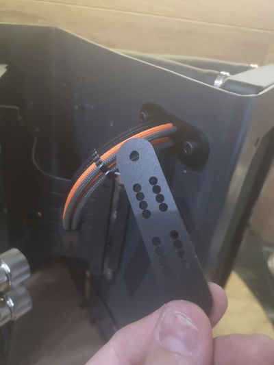
Next step was doing as much cutting and drilling as I could, I didn't want to do any after painting. The plan was to cut out holes for the cables and use a panel mount comb, this was 1 revision as last time I put each wire through the case which was tedious and made upgrades iffy.
I needed holes for 24 pin, 8 pin, 8+8 Pcie, RGB, fan headers, power button, bulkhead fitting and pump PWM. Also some drill and tapped holes for the panel combs to mount to.
Involved me doing small bit and stepping up, or the bigger holes using a step bit too. I made oval shapes for the panel mount combs and did the same method for RGB and fan headers.
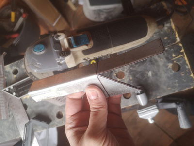
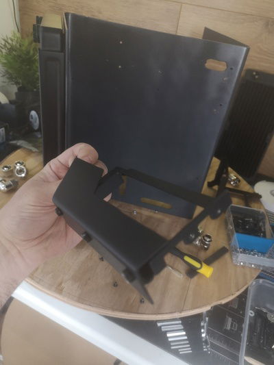
Next I moved onto a PSU bracket which I made from some angle steel, made 4 holes for case mounting and cut away material which interfered with AC power or switches, it actually only used the 2 lower screws but test fitting was solid with little movement.
Forgot to take some pictures during the process but you get the idea.
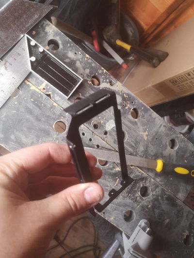
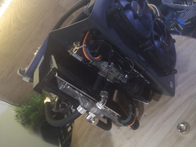
Next I did some test fitting and had some ideas about the GPU mount. It went through some several iterations and using a vertical mounting kit, but in the end I just used the GPU fixing side for the IO tab and made my own 45 degree bracket from the same angle steel. Only thing I didn't do here was some welds to join the steel together where I removed a 45 degree piece. This left a 45 degree bent fixing area which was mounted above the radiator and attached the riser bracket to the other part.
Also some finished parts during assembly
![User Image]()
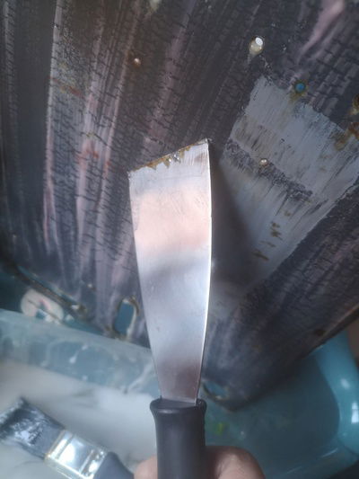
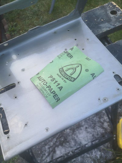
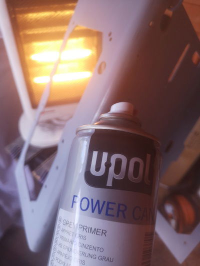
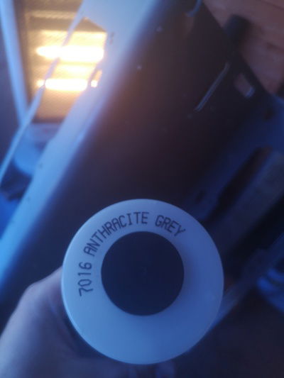
I painted the hand made brackets in black and used a chemical strip on the Z chassis. After the chemicals took effect i did another coat, left it and the did a combination of scraping followed by a water hose and a scrubbing brush. Once it was complete I went over with 400 wet sanding all over removing some left over primer and any residual paint. Took this back to bare metal and left in front of a heater to completely dry. Next day i used the same heater to warm the surface area and did a primer base with a 2 day cure, followed by a 1000 grit very gently just to remove any raised areas or dust that may have got into the coat. Then a tack cloth over the whole area followed by some panel wipe. Then I applied the base coat of anthracite grey from the previous build, first coat went on well, but same issues occurred where the paint would apply patchy as I can’t fully get square with the case and dry paint manages to get onto the top and bottom of the Z. Was much better than my 1st build so I had improved somewhat, I left that to cure for 48 hours before I did some assembly.
![User Image]()
![User Image]()
![User Image]()
![User Image]()
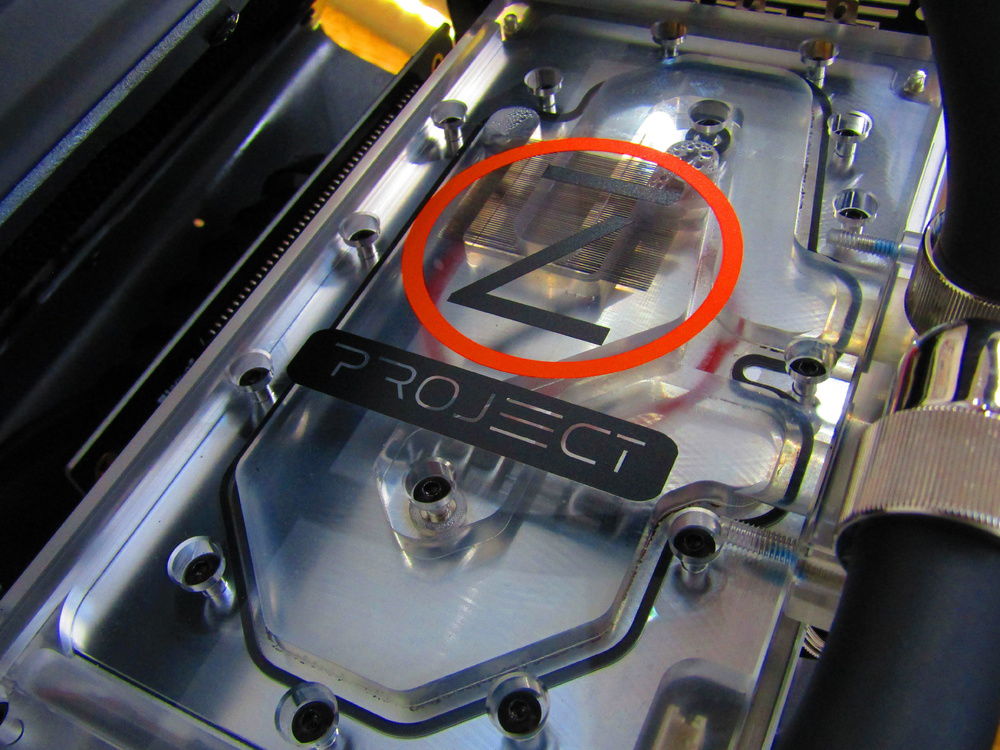
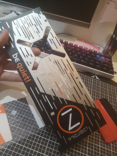
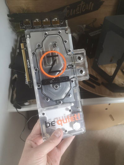
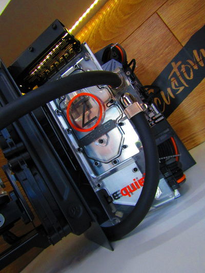
I did some vinyl / sticker lettering on the GPU in the meantime, wanted to add my sponsor for this build be quiet! and the project title Project Z.
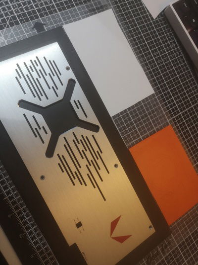
Hardest part was trying to incorporate a design on the backplate but I think it came off well. I used a picture of the backplate, cropped it and resized it to the same measurements of the backplate.
Tried to copy the line design and black out the Vega red logo and add some text. On the front was simply adding the logos again.
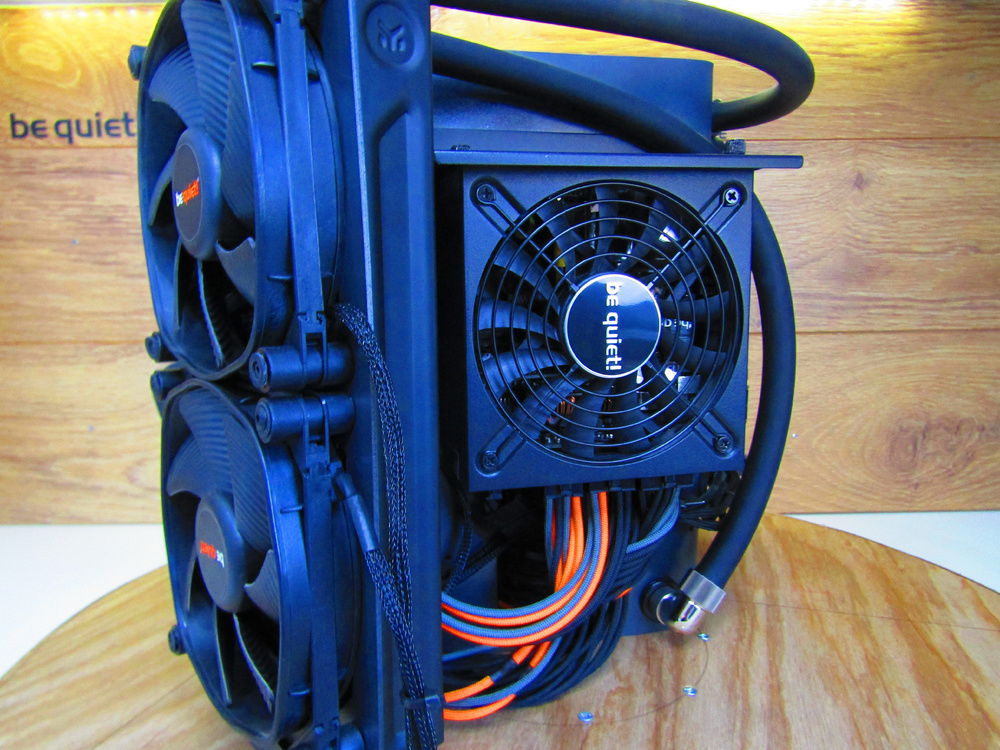
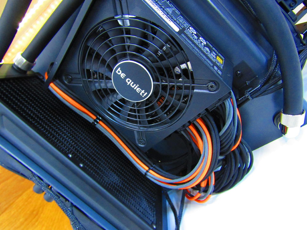
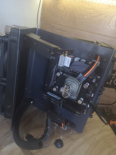
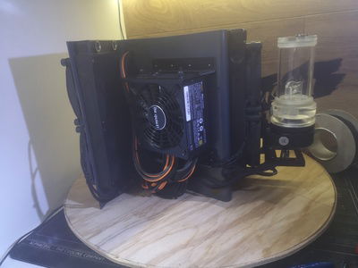
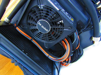
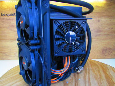
Next was assembly, starting with the PSU bracket as it had to go in first before the motherboard, then the GPU bracket as the radiator would be in the way. Radiators and fans were added next followed by the motherboard and power supply.
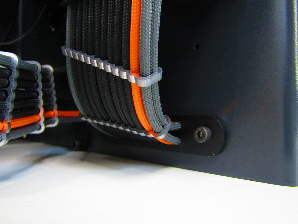
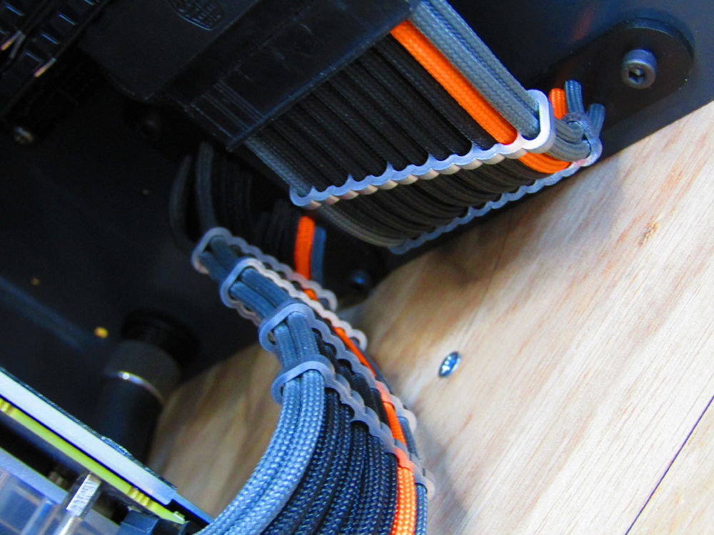
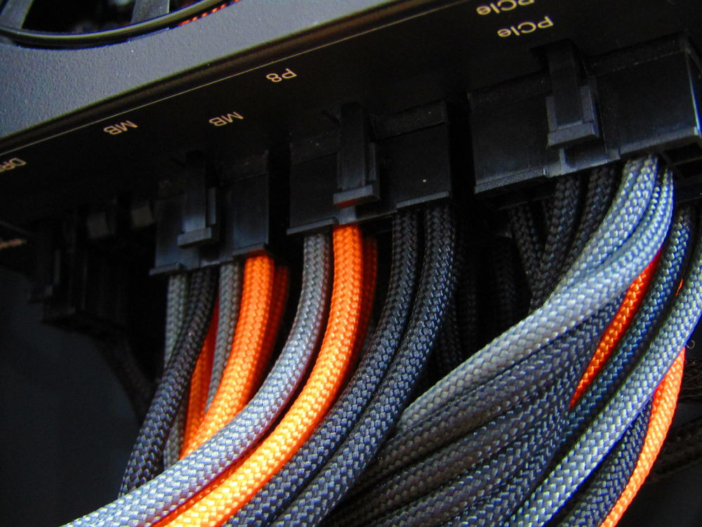
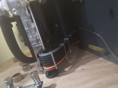
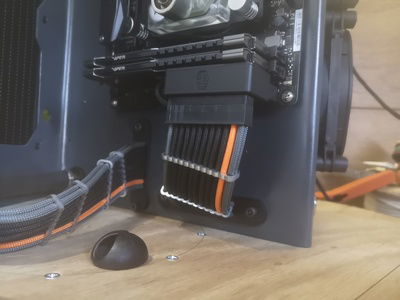
From here I began making cables as I now had a rough length for 24 pin, PCIE and EPS cables. I have had a small CNC 3018 pro for about 6 months and after finally getting round to setting it up I designed some cable combs to panel mount to the chassis. I was really impressed with how they came out and has opened up a whole new world for me so expect to see more things in the future.
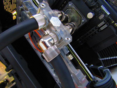
I went with a black, orange and gunmetal design with aluminium effect combs to match the nickel silver EKWB fittings. I actually did the 24 a little short my mistake, miss judging the arc in the cable but I fixed this with a coolermaster 24 pin 90 degree adaptor which I had at hand,
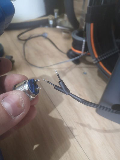
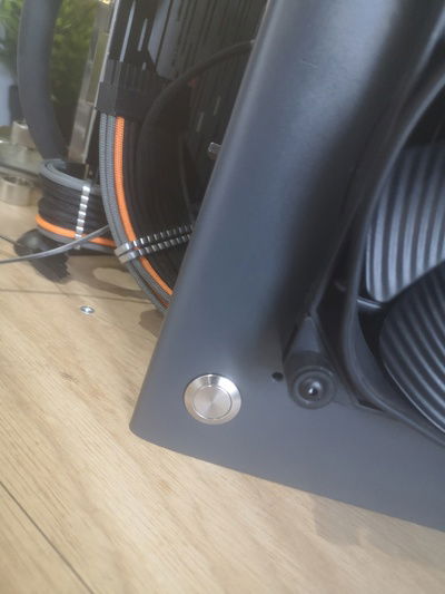
Next I started to route some cables, mainly PWM fan, pump and RGB wires. The last fiddly job was the power button, it actually ran in the dummy 20 pin slot and is super discrete as you cant see it at all. Simple 16mm vandalism button under the rear radiator and the header is just off the 24 pin, this was sleeved black for some extra stealth.
Plumbing
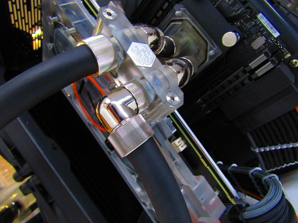
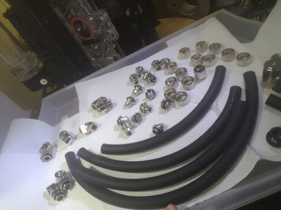
I actually pre done and I knew what fittings I was using, the only parts I didn’t do was the GPU to CPU tubes as the motherboard was in my daily driver and could afford any downtime.
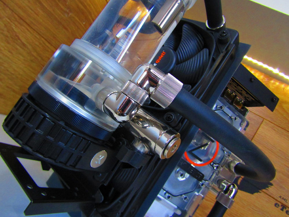
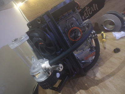
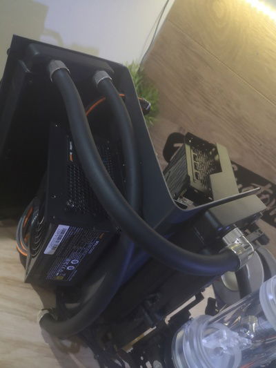
So it ended up in a parallel layout going from the pump to the GPU CPU back to the GPU to a bulkhead fitting, running up to the rear radiator back to the front then to the reservoir.
It was important as I think not doing the parallel run would ruin the look, as one of the most difficult parts is going through or around the case and as the angles in the chassis are not 90 or 45 for example. Doing this in hardline again would be much more difficult. Overall, very happy.
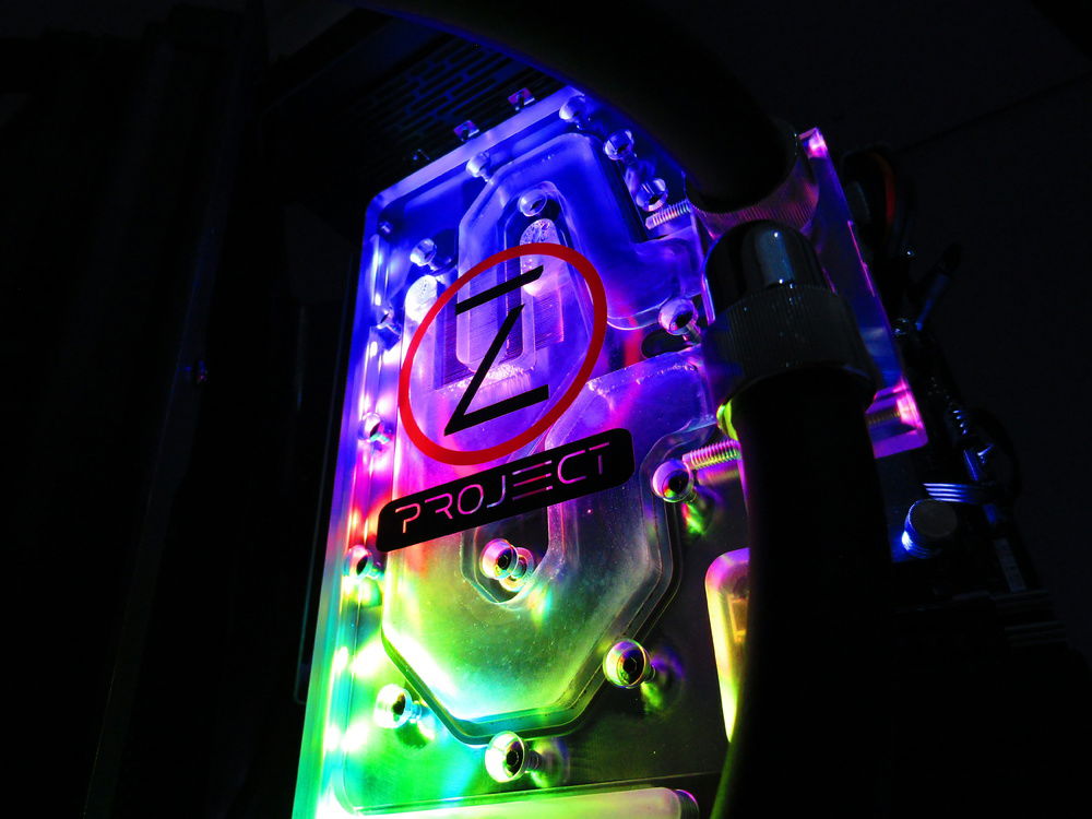
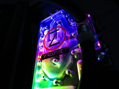
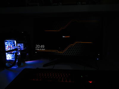
Next I did a leak test with the EKWB tester. I think I prefer the old method, but it did come in handy. Think it's not the most suitable method, especially after what seemed like 1 or 2% change over a half an hour test. I just went ahead and threw in the EK clear cryofuel. I went with the clear as I wanted to see some RGB, option 2 was pastel orange but I had some plans for this build afterwards so clear was the best option.
Obviously I had no leaks, no issues. I only cycled it for 30 mins with a few on and offs then moved it to my work area for first boot. I did some gaming and vented the air a few times, usually I would have just ran the pump but a D5 with no PWM is super fast. I thought this was more of a risk.
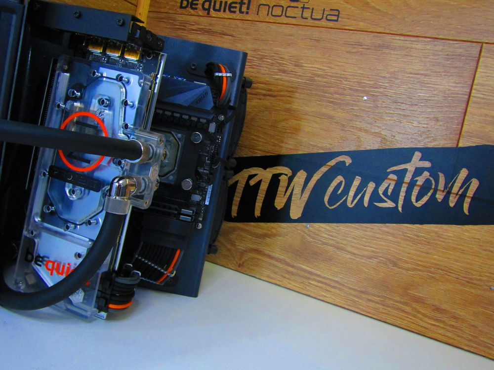
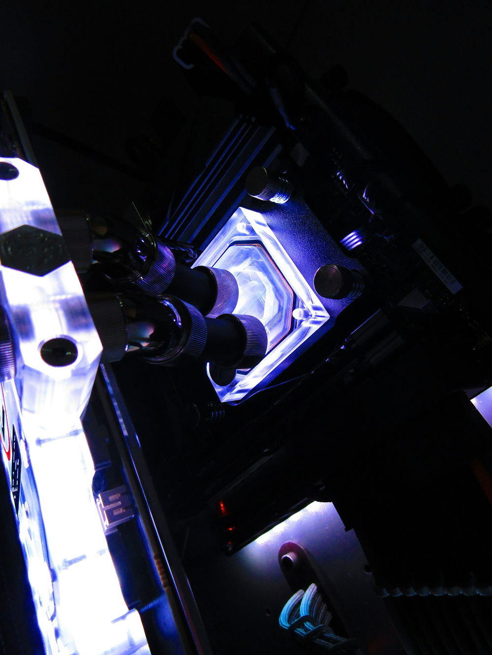
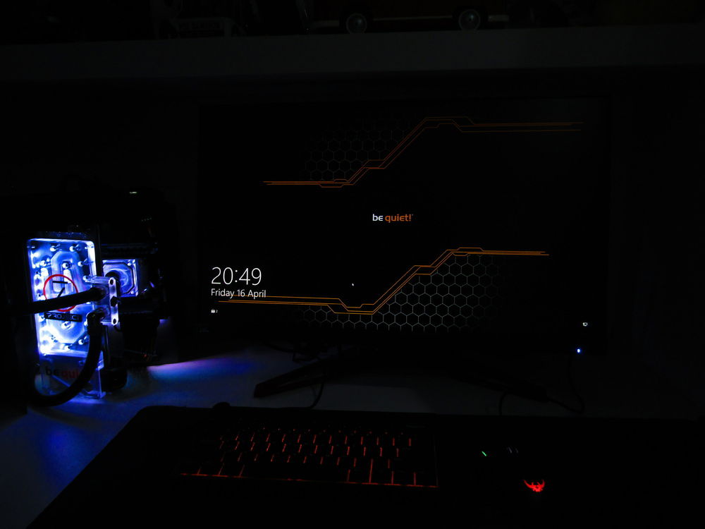
After using the PC for a few weeks with no issues I took some final pictures for be quiet! and has been selected again to appear in Custom PC magazine. Super happy about that, it has been well received online, fellow modders and friends.
Here they are so enjoy, thank you for your time.
