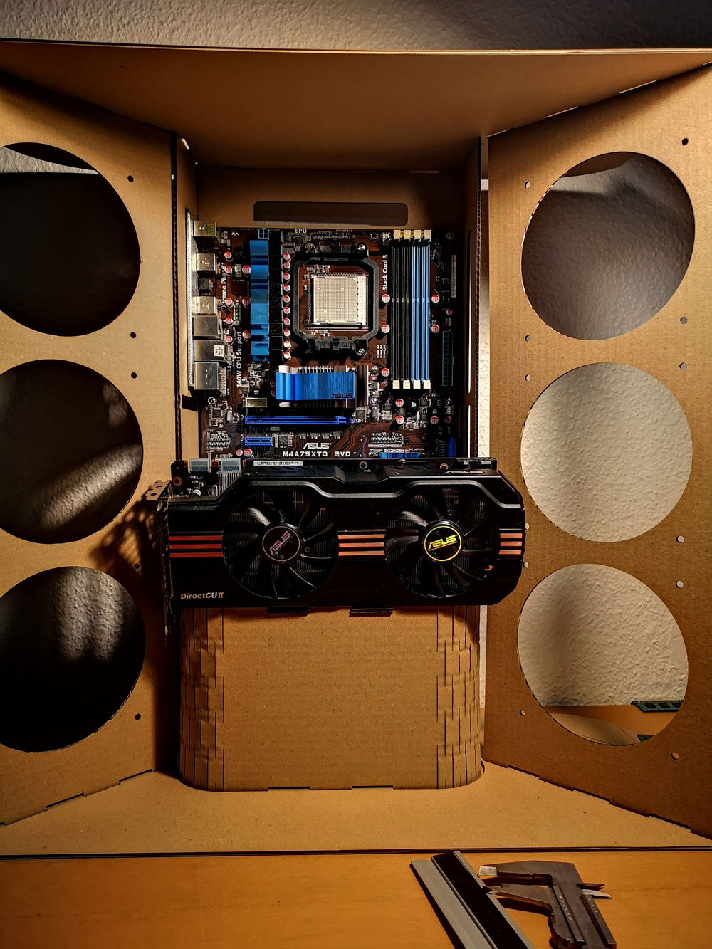
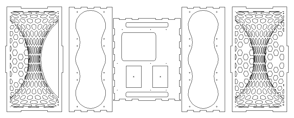
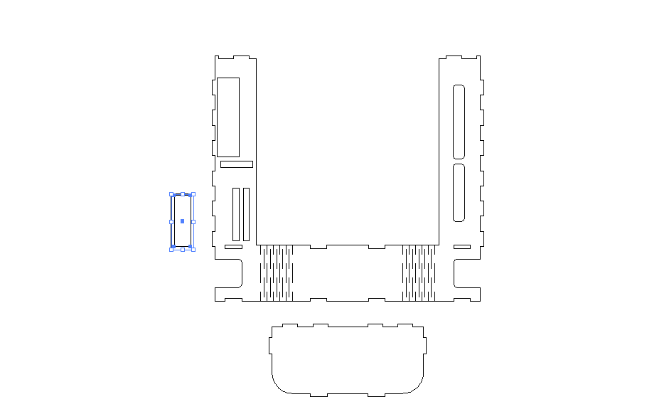
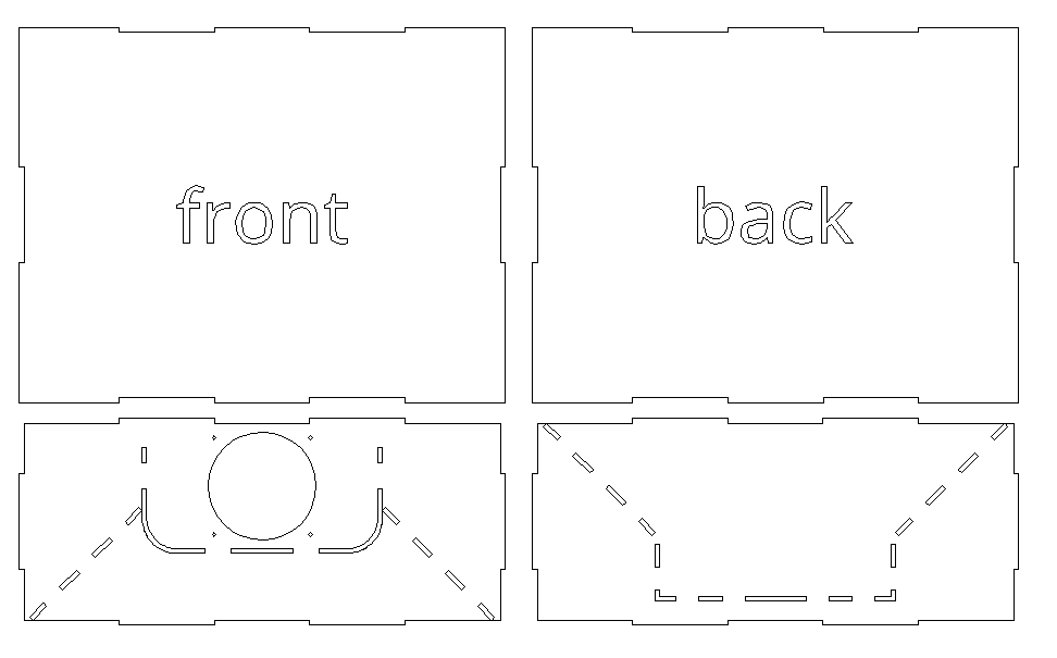
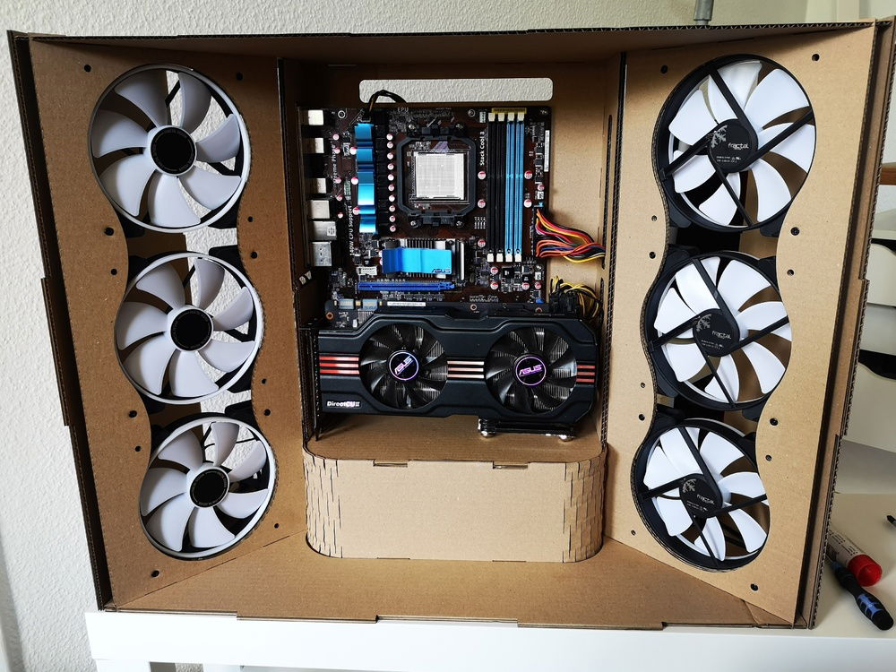
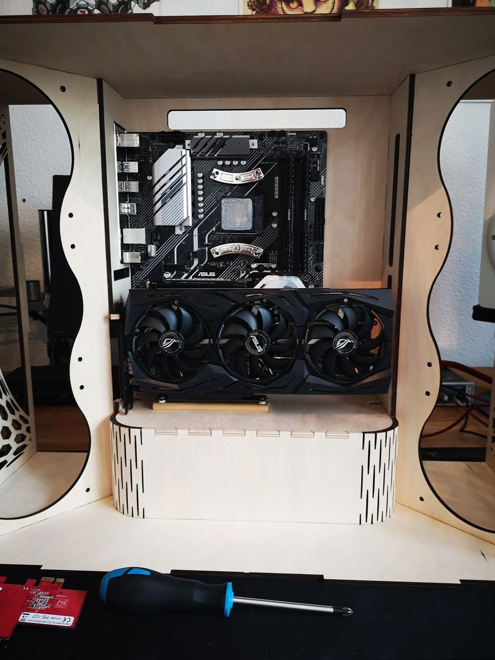
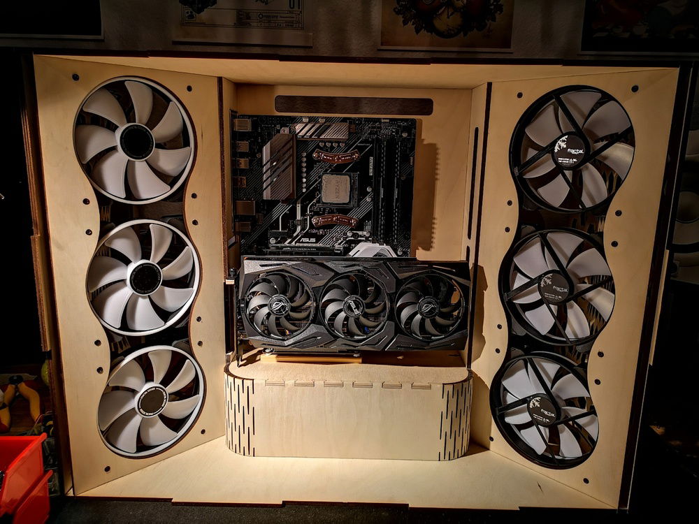
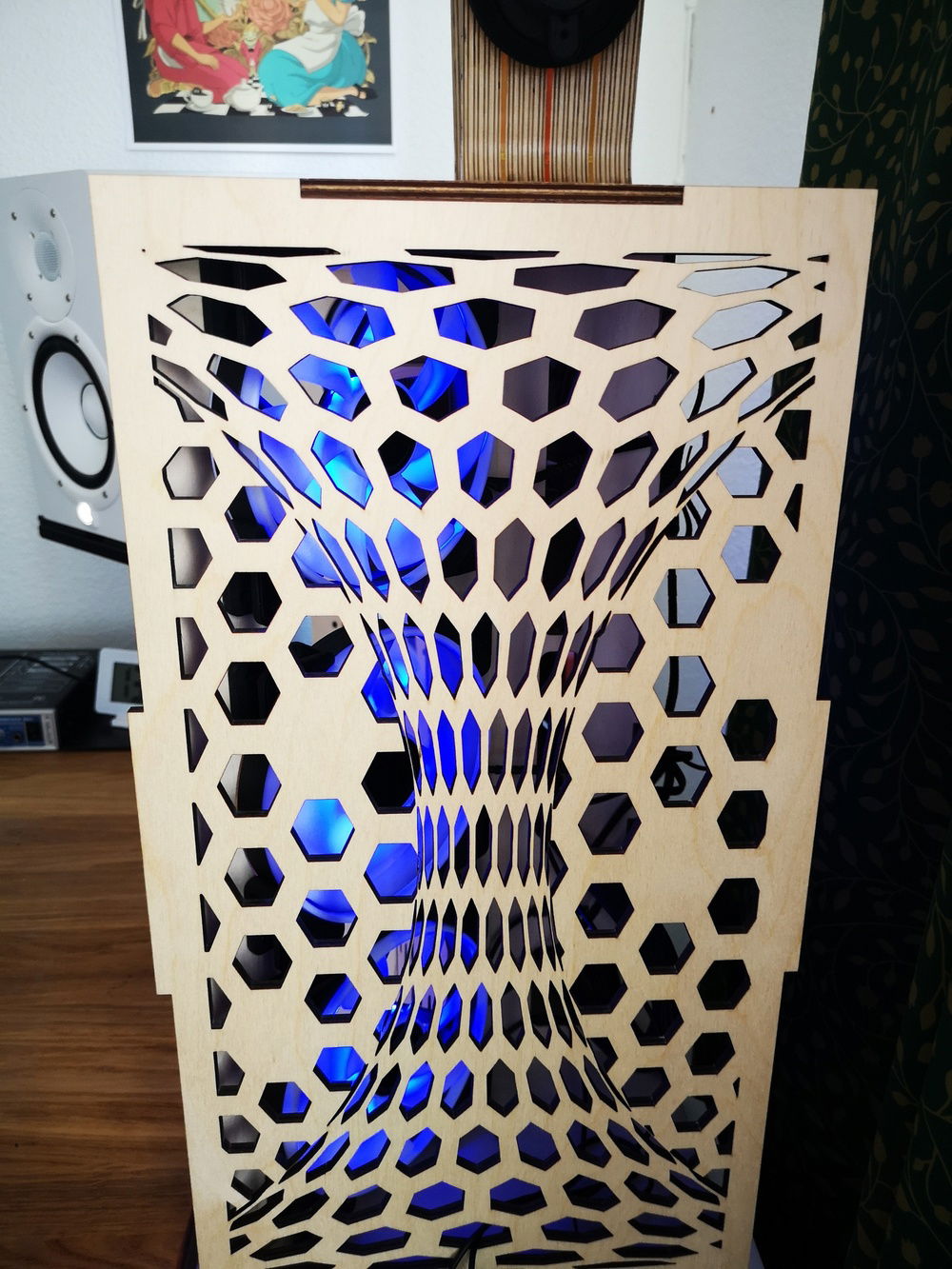
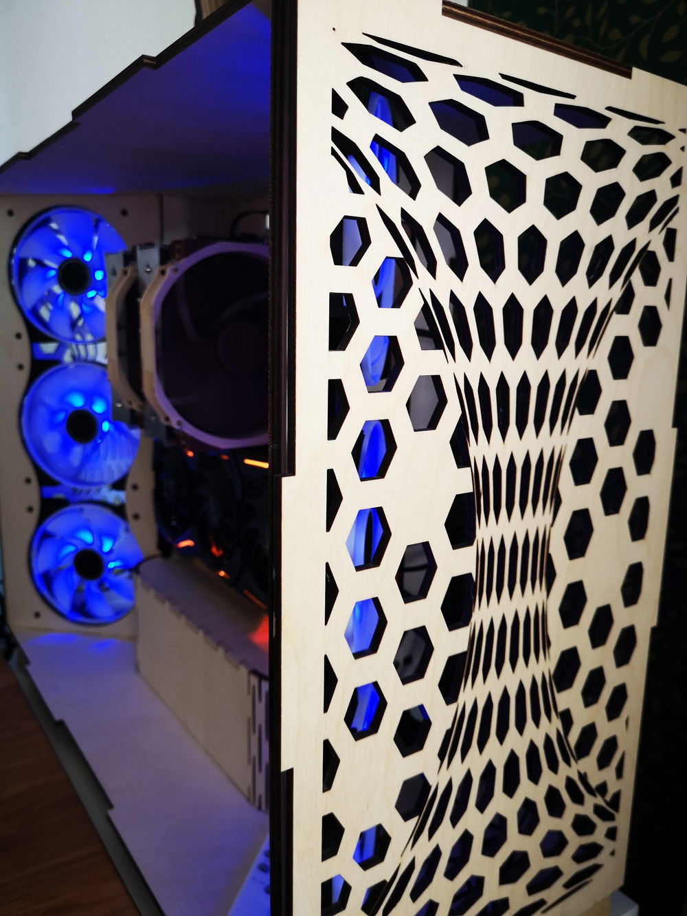
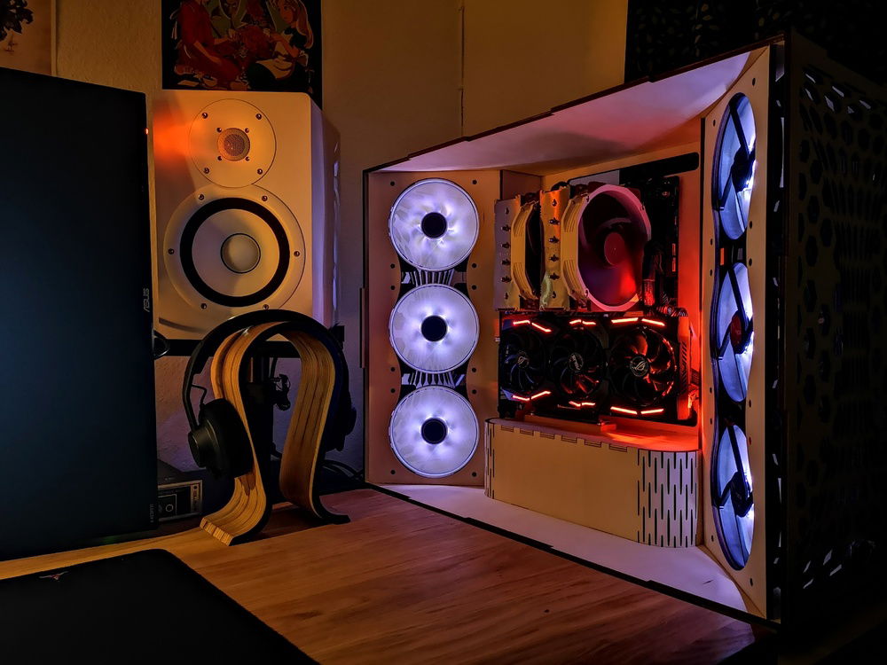
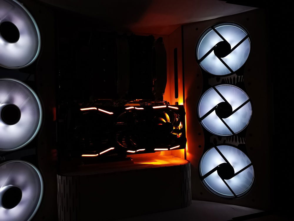
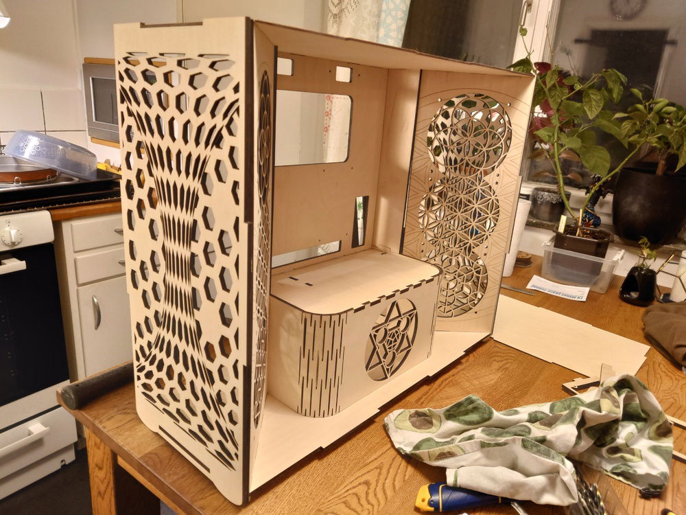
Laser cut Torus case scratch build
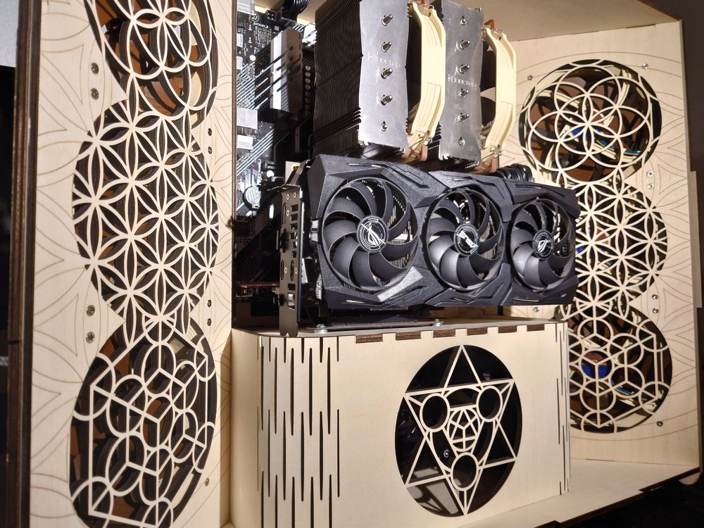
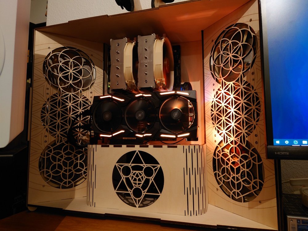
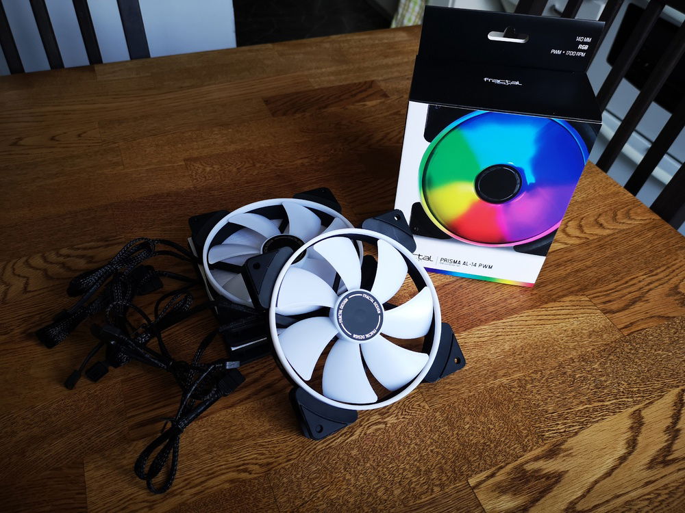
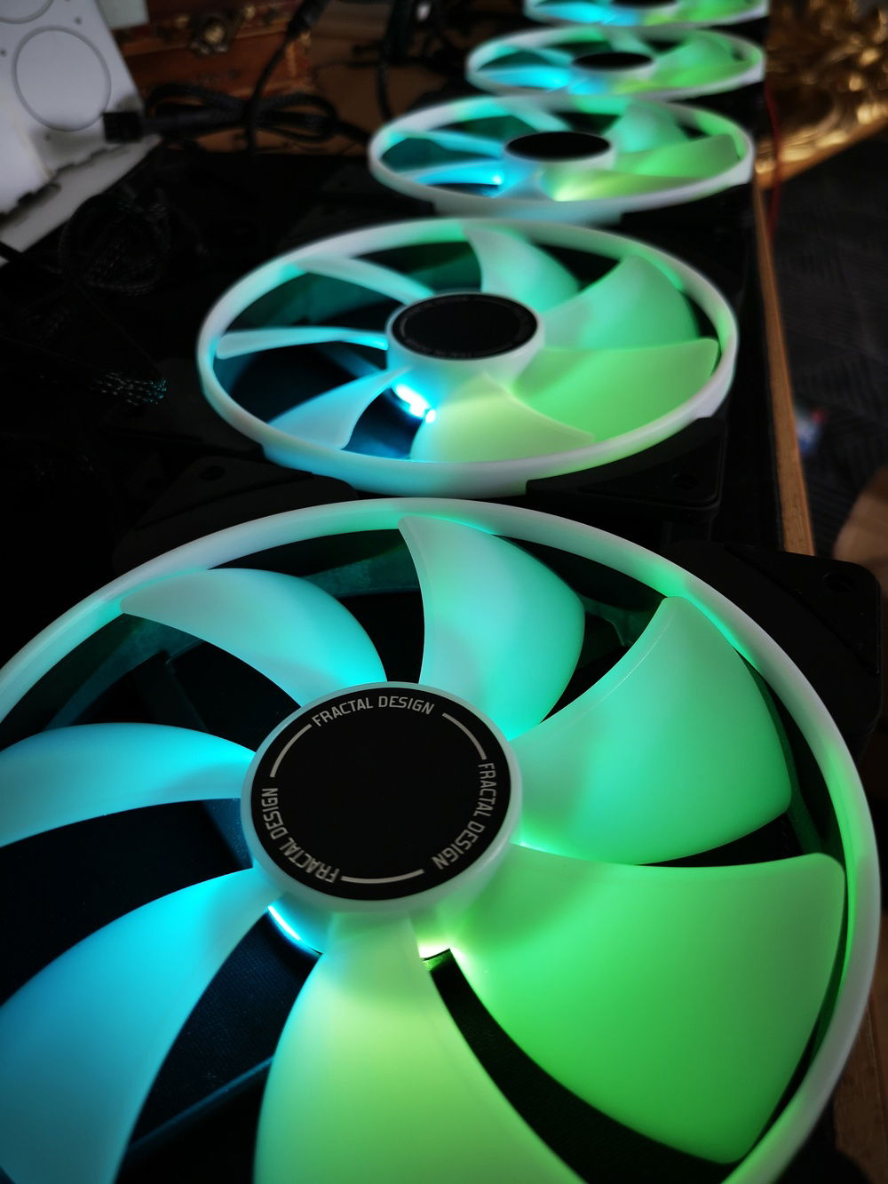
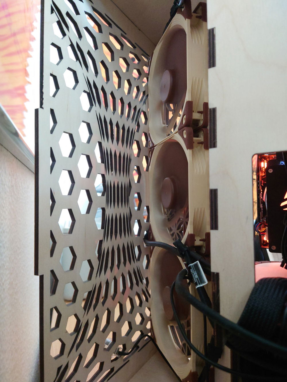
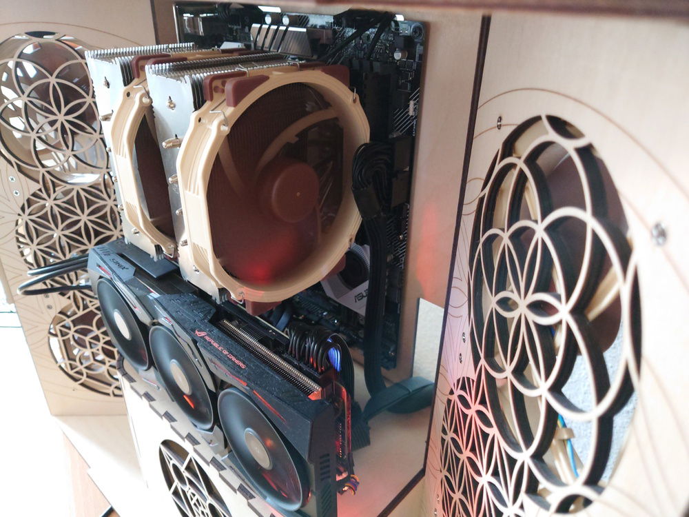
In the recent virus outbreak I found the time to invest in some pc parts. It is a modest build that should last me around ten years without any major updates, however I wanted to have the opportunity to expand later. Therefore, I focused on good cooling. I dont have OC in mind but maybe later!
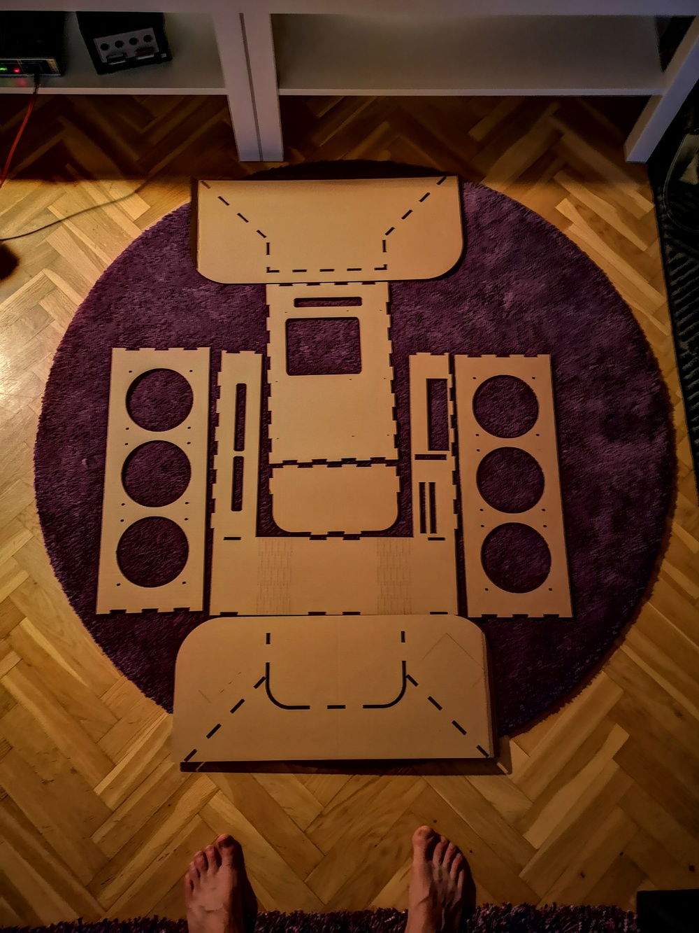
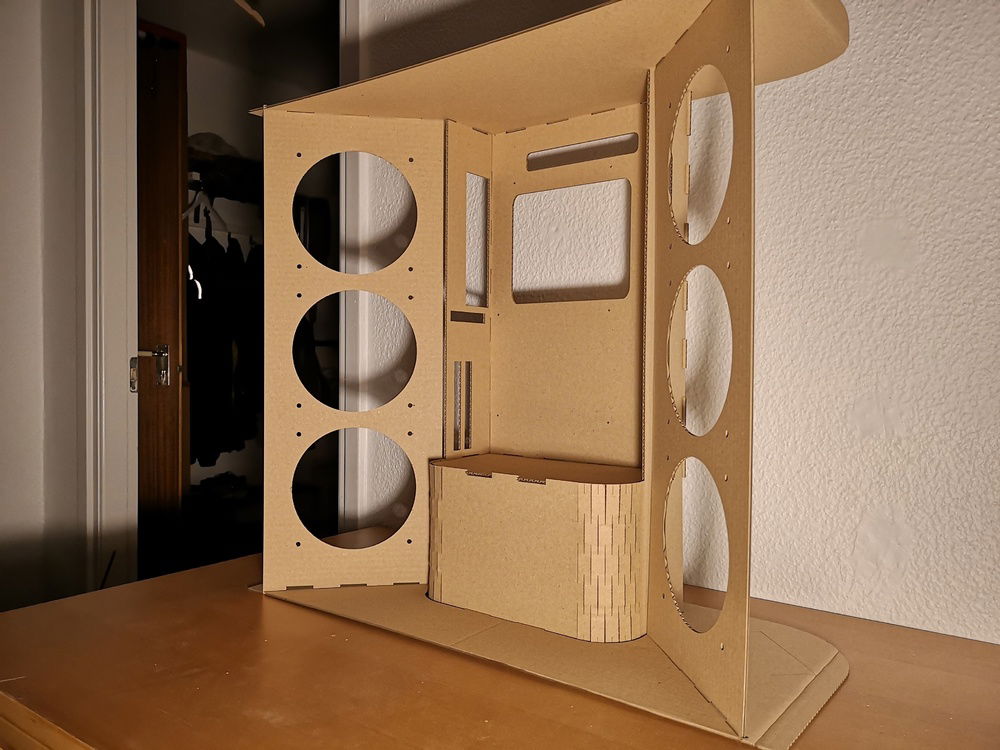
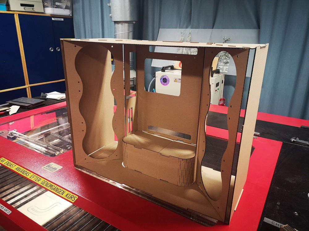
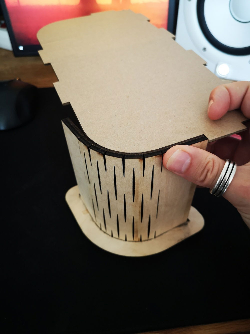
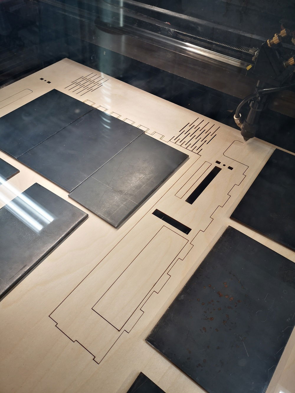
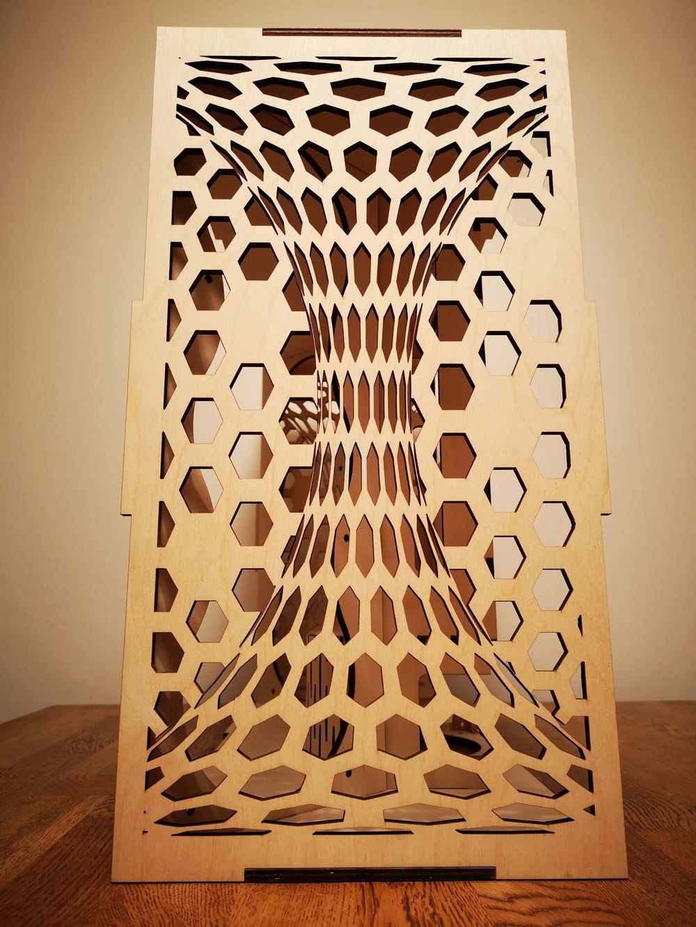
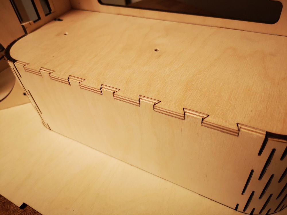
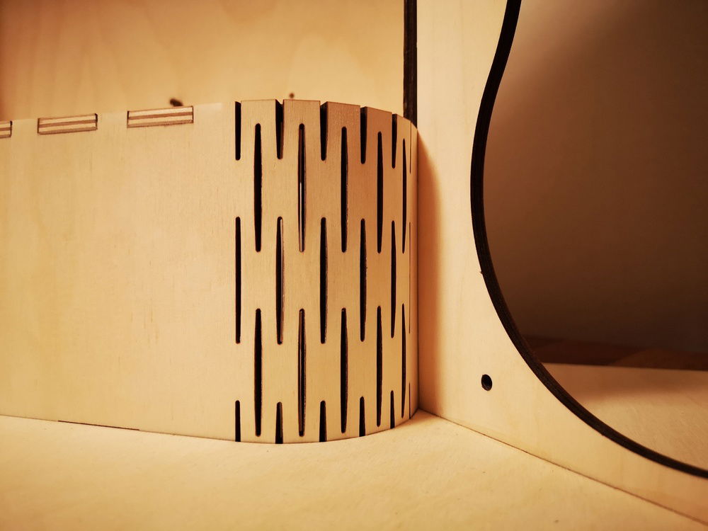
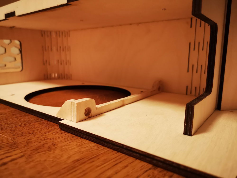
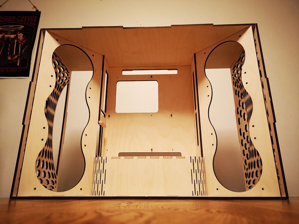
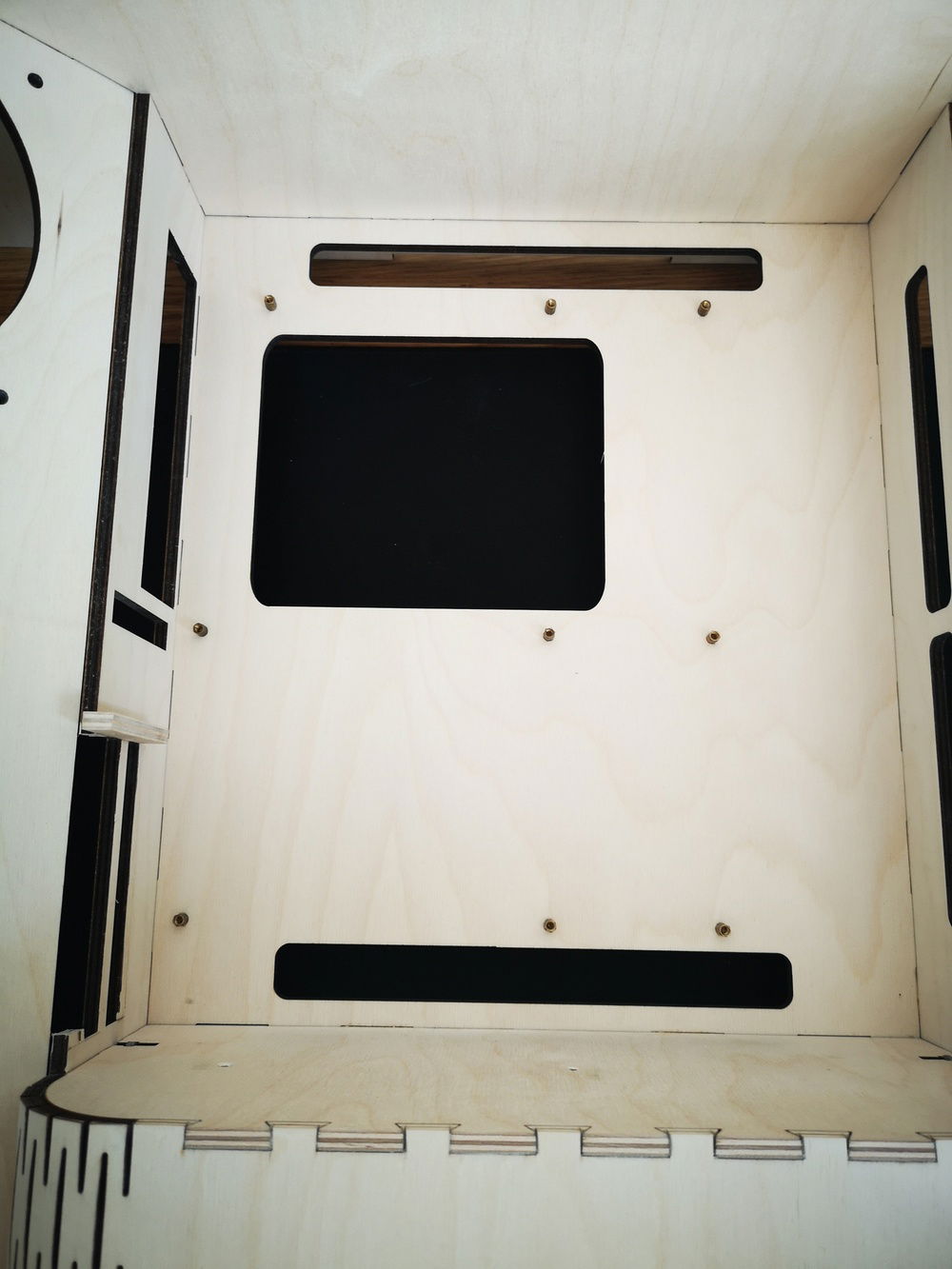
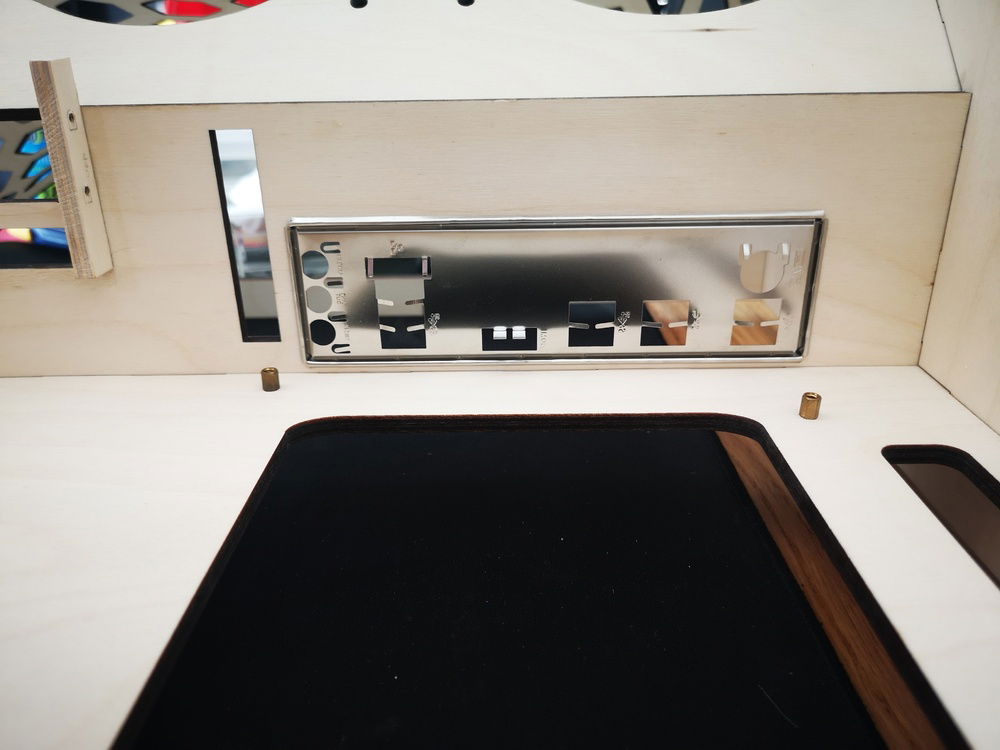
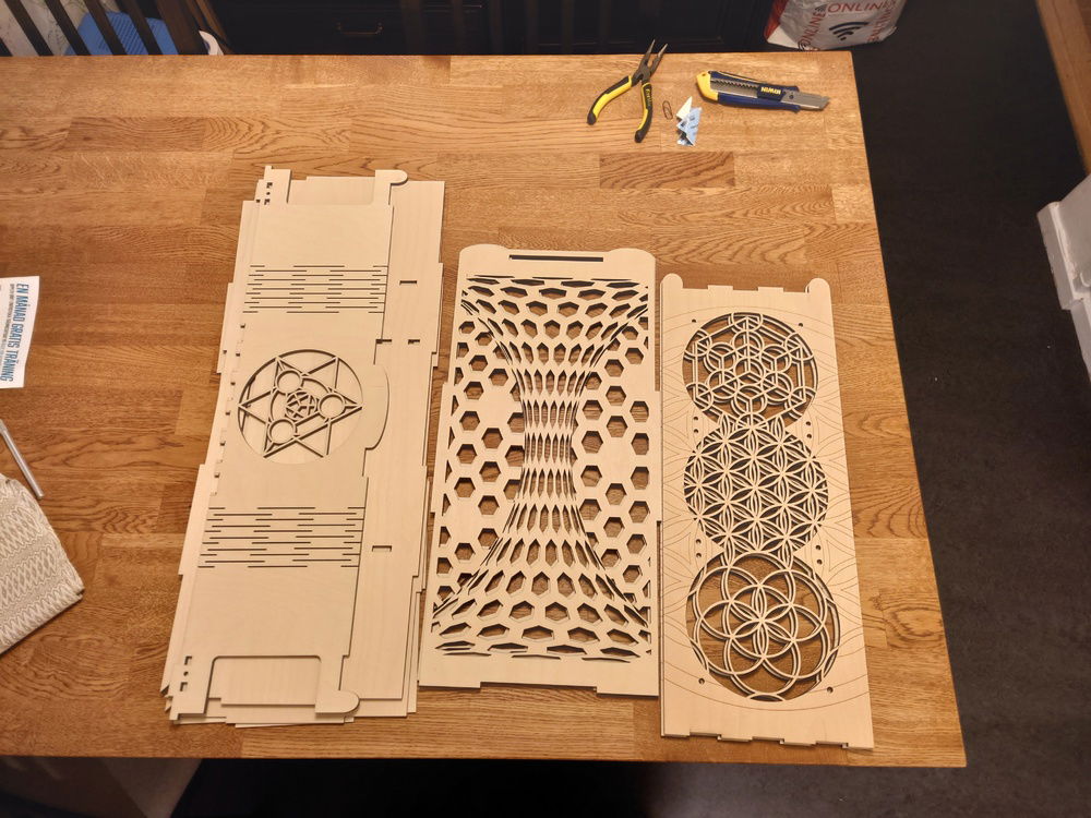
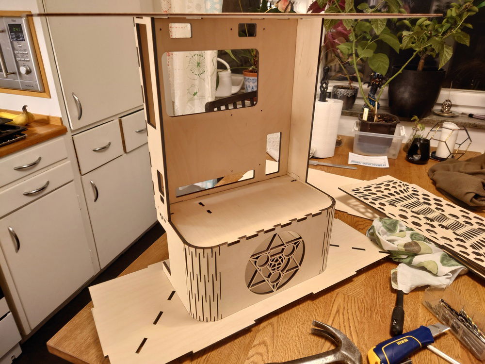
Paired with this, I have a hobby. At my local MakerSpace, we have a laser cutter I have used quite a lot so I want to challenge myself to make the case out of plywood and acrylic where as much as possible should be done by the laser. When I had finished the design more or less I found a really interesting build here from TerHorstCustoms . It is his tweaked Meshify S2. Check it out! Since I dont have any size limitations I did not copy his measurements but his idea is very prevalent in this build.
Paired with this, I have a hobby. At my local MakerSpace, we have a laser cutter I have used quite a lot so I want to challenge myself to make the case out of plywood and acrylic where as much as possible should be done by the laser. When I had finished the design more or less I found a really interesting build here from TerHorstCustoms . It is his tweaked Meshify S2. Check it out! Since I dont have any size limitations I did not copy his measurements but his idea is very prevalent in this build.
Color(s): Black
RGB Lighting? Yes
Theme: Art
Cooling: Air Cooling
Size: ATX
Type: General Build
Contests
This build participated in 1 contest.
| Rank | Contest | Date |
|---|---|---|
| #9 | Build of the Month - May 2021 | ended |
Build Updates
Color profiles
Mounting and testing the feels
Lasercut plywood
Getting closer to a final design
Prototype 2 test fit
Hardware
CPU
$ 79.99
Motherboard
$ 290.99
Memory
$ 617.90
Graphics
$ 504.75
Case
$ 207.03
Case Fan
$ 149.70
Cooling
$ 129.95
Monitor
$ 390.00
ASUS - Asus VH242H 23.6-Inch Full-HD 5 ms LCD Monitor (2x)
Size: 23.6 Inch
Panel: TN
Refresh Rate: 60 Hz
Keyboard
$ 93.99
Estimated total value of this build:
$ 2,601.49
Approved by:
